Ethernet Subsystem Registers
www.ti.com
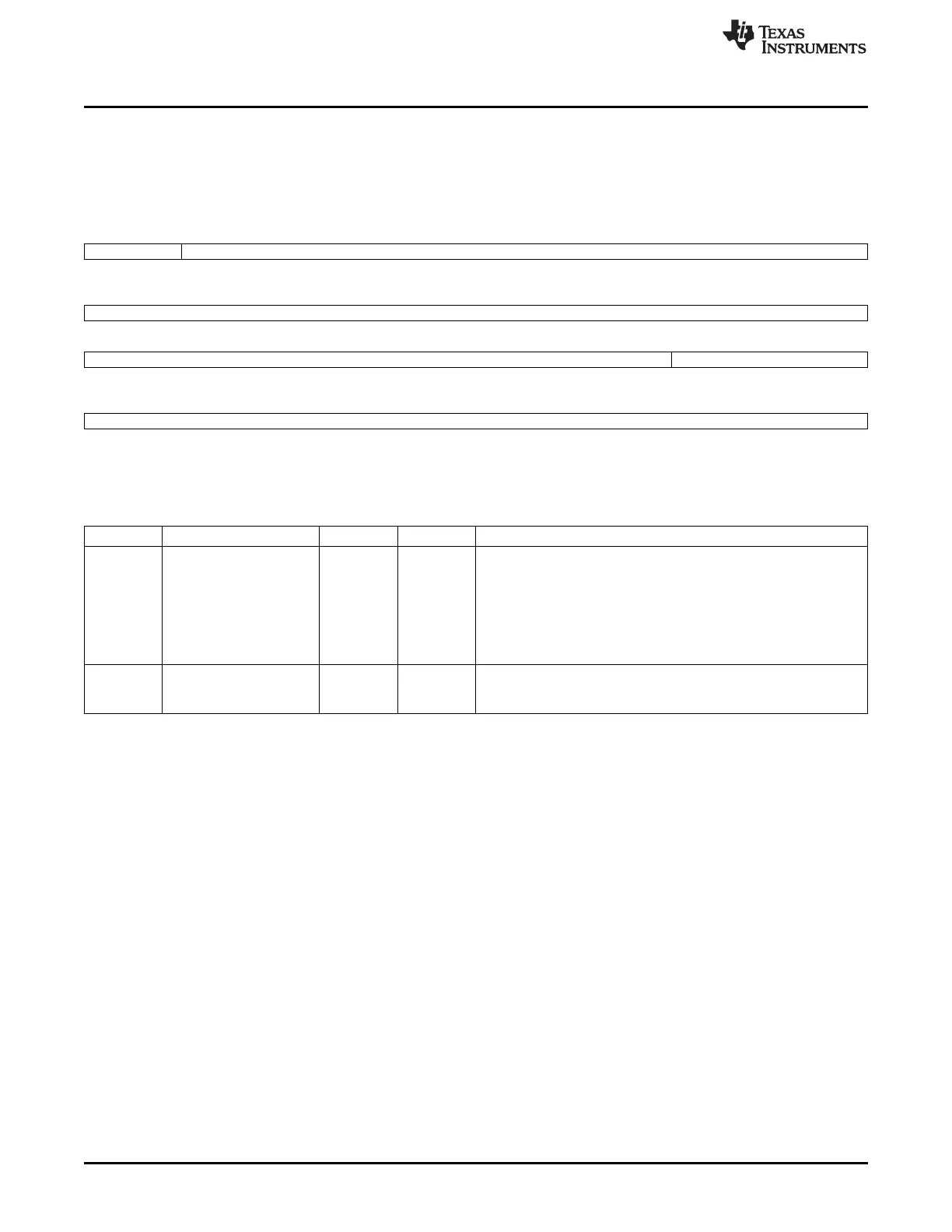
14.5.1.5 TBLCTL Register (offset = 20h) [reset = 0h]
TBLCTL is shown in Figure 14-19 and described in Table 14-29.
ADDRESS LOOKUP ENGINE TABLE CONTROL
Figure 14-19. TBLCTL Register
31 30 29 28 27 26 25 24
WRITE_RDZ Reserved
R/W-0
23 22 21 20 19 18 17 16
Reserved
15 14 13 12 11 10 9 8
Reserved ENTRY_POINTER
R/W-0
7 6 5 4 3 2 1 0
ENTRY_POINTER
R/W-0
LEGEND: R/W = Read/Write; R = Read only; W1toCl = Write 1 to clear bit; -n = value after reset
Table 14-29. TBLCTL Register Field Descriptions
Bit Field Type Reset Description
31 WRITE_RDZ R/W-0 0 Write Bit - This bit is always read as zero.
Writing a 1 to this bit causes the three table word register values to
be written to the entry_pointer location in the address table.
Writing a 0 to this bit causes the three table word register values to
be loaded from the entry_pointer location in the address table so that
they may be subsequently read.
A read of any ALE address location will be stalled until the read or
write has completed.
9-0 ENTRY_POINTER R/W-0 0 Table Entry Pointer - The entry_pointer contains the table entry
value that will be read/written with accesses to the table word
registers.
1246
Ethernet Subsystem SPRUH73H–October 2011–Revised April 2013
Submit Documentation Feedback
Copyright © 2011–2013, Texas Instruments Incorporated

 Loading...


