www.ti.com
DMTimer 1ms
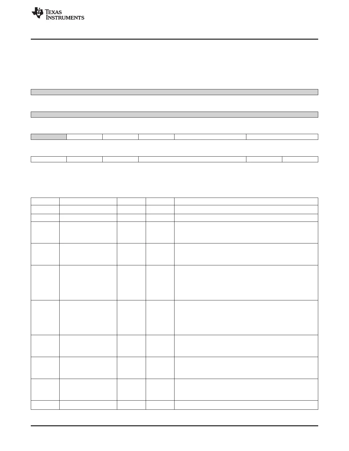
20.2.5.7 TCLR Register (offset = 24h) [reset = 0h]
TCLR is shown in Figure 20-41 and described in Table 20-42.
This register controls optional features specific to the timer functionality
Figure 20-41. TCLR Register
31 30 29 28 27 26 25 24
Reserved
R-0h
23 22 21 20 19 18 17 16
Reserved
R-0h
15 14 13 12 11 10 9 8
Reserved GPO_CFG CAPT_MODE PT TRG TCM
R-0h R/W-0h R/W-0h R/W-0h R/W-0h R/W-0h
7 6 5 4 3 2 1 0
SCPWM CE PRE PTV AR ST
R/W-0h R/W-0h R/W-0h R/W-0h R/W-0h R/W-0h
LEGEND: R/W = Read/Write; R = Read only; W1toCl = Write 1 to clear bit; -n = value after reset
Table 20-42. TCLR Register Field Descriptions
Bit Field Type Reset Description
31-15 Reserved R 0h
Reads return 0
14 GPO_CFG R/W 0h
13 CAPT_MODE R/W 0h
Capture mode select bit (first/second)
0 = First_capt : Capture the first enabled capture event in TCAR1
1 = Sec_capt : Capture the second enabled capture event in TCAR2
12 PT R/W 0h
Pulse or Toggle select bit
0 = pulse : pulse modulation
1 = toggle : toggle modulation
11-10 TRG R/W 0h
Trigger Output Mode
0 = no_trg : No trigger
1 = ovf_trg : Overflow trigger
2 = ovf_mat_trg : Overflow and match trigger
3 = reserved : Reserved
9-8 TCM R/W 0h
Transition Capture Mode
0 = no_edge : No capture
1 = rise_edge : Capture on rising edges of PIEVETCAPT
2 = fall_edge : Capture on falling edges of PIEVETCAPT
3 = booth_edges : Capture on booth edges of PIEVETCAPT
7 SCPWM R/W 0h
Pulse Width Modulation output pin default value
0 = def_low : default value of PORPWM: 0
1 = def_high : default value of PORPWM: 1
6 CE R/W 0h
Compare enable
0 = dsb_cmp : Compare disabled
1 = enb_cmp : Compare enabled
5 PRE R/W 0h
Prescaler enable
0 = no_prescal : Prescaler disabled
1 = prescal_on : Prescaler enabled
4-2 PTV R/W 0h
Trigger Output Mode
3605
SPRUH73H–October 2011–Revised April 2013 Timers
Submit Documentation Feedback
Copyright © 2011–2013, Texas Instruments Incorporated

 Loading...


