USB Registers
www.ti.com
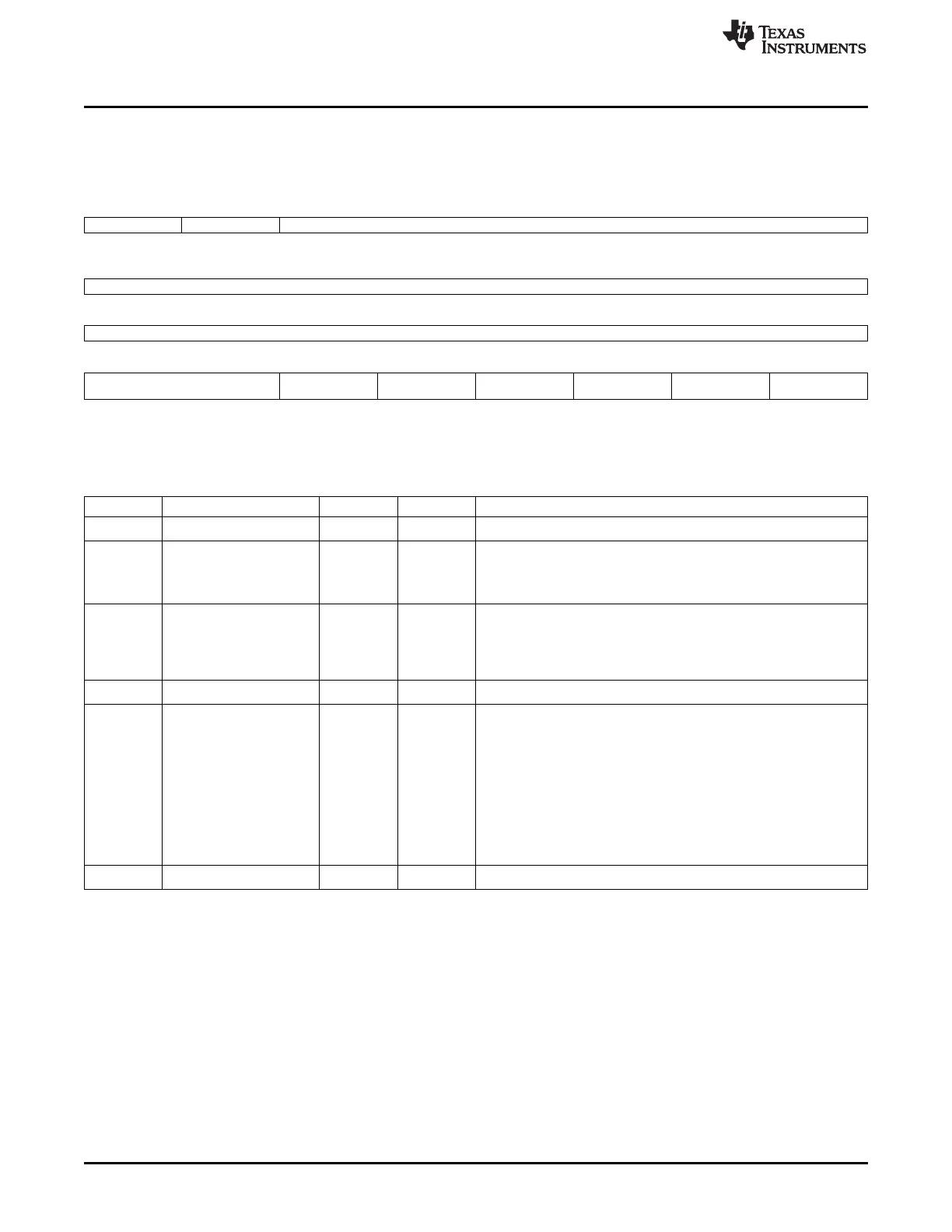
16.5.3.2 USB1CTRL Register (offset = 14h) [reset = 0h]
USB1CTRL is shown in Figure 16-100 and described in Table 16-110.
Figure 16-100. USB1CTRL Register
31 30 29 28 27 26 25 24
DIS_DEB DIS_SRP Reserved
R/W-0h R/W-0h
23 22 21 20 19 18 17 16
Reserved
15 14 13 12 11 10 9 8
Reserved
7 6 5 4 3 2 1 0
Reserved SOFT_RESET_ISOLA RNDIS UINT Reserved CLKFACK SOFT_RESET
TION
R/W-0h R/W-0h R/W-0h R/W-0h R/W-0h
LEGEND: R/W = Read/Write; R = Read only; W1toCl = Write 1 to clear bit; -n = value after reset
Table 16-110. USB1CTRL Register Field Descriptions
Bit Field Type Reset Description
31 DIS_DEB R/W 0h
Disable the VBUS debouncer circuit fix
30 DIS_SRP R/W 0h Disable the OTG Session Request Protocol (SRP) AVALID circuit fix.
When enabled (=0) this allows additional time for the VBUS signal to
be measured against the VBUS thresholds.
The time is specified in the USB0 SRP Fix Time Register.
5 SOFT_RESET_ISOLATIO R/W 0h Soft reset isolation.
N When high this bit forces all USB1 signals that connect to the
USBSS to known values during a soft reset via bit 0 of this register.
This bit should be set high prior to setting bit 0 and cleared after bit 0
is cleared.
4 RNDIS R/W 0h
Global RNDIS mode enable for all endpoints.
3 UINT R/W 0h USB interrupt enable
1 = Legacy
0 = Current (recommended setting)
If uint is set high, then the mentor controller generic interrupt for
USB[9] will be generated (if enabled).
This requires S/W to read the mentor controller's registers to
determine which interrupt from USB[0] to USB[7] that occurred.
If uint is set low, then the usb20otg_f module will automatically read
the mentor controller's registers and set the appropriate interrupt
from USB[0] to USB[7] (if enabled).
The generic interrupt for USB[9] will not be generated.
1 CLKFACK R/W 0h
Clock stop fast ack enable.
1856
Universal Serial Bus (USB) SPRUH73H–October 2011–Revised April 2013
Submit Documentation Feedback
Copyright © 2011–2013, Texas Instruments Incorporated

 Loading...


