Power, Reset, and Clock Management
www.ti.com
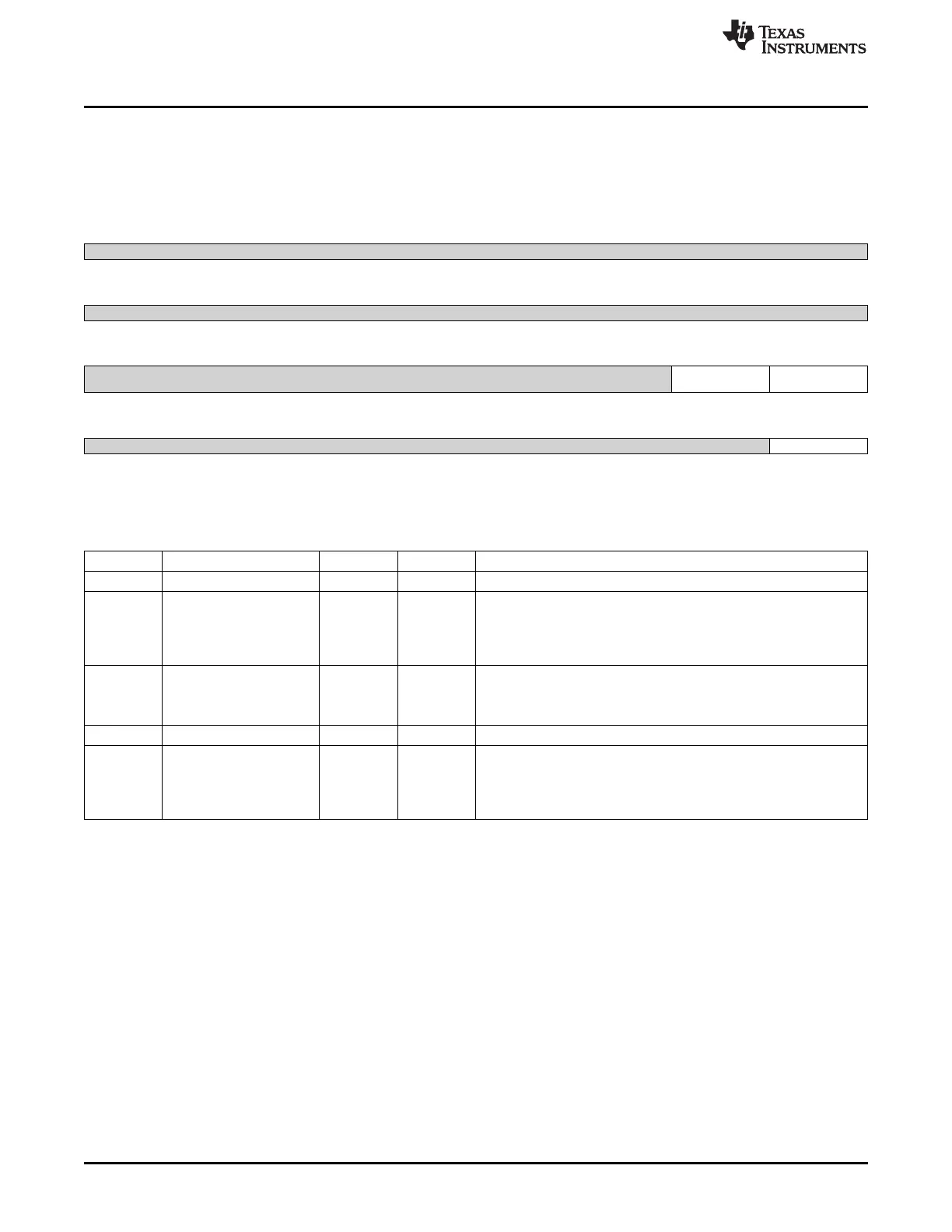
8.1.13.5.6 PRM_LDO_SRAM_CORE_CTRL Register (offset = 14h) [reset = 0h]
PRM_LDO_SRAM_CORE_CTRL is shown in Figure 8-184 and described in Table 8-203.
Control and status of the SRAM LDO for CORE voltage domain. [warm reset insensitive]
Figure 8-184. PRM_LDO_SRAM_CORE_CTRL Register
31 30 29 28 27 26 25 24
Reserved
R-0h
23 22 21 20 19 18 17 16
Reserved
R-0h
15 14 13 12 11 10 9 8
Reserved SRAM_IN_TRANSITI SRAMLDO_STATUS
ON
R-0h R-0h R-0h
7 6 5 4 3 2 1 0
Reserved RETMODE_ENABLE
R-0h R/W-0h
LEGEND: R/W = Read/Write; R = Read only; W1toCl = Write 1 to clear bit; -n = value after reset
Table 8-203. PRM_LDO_SRAM_CORE_CTRL Register Field Descriptions
Bit Field Type Reset Description
31-10 Reserved R 0h
9 SRAM_IN_TRANSITION R 0h
Status indicating SRAM LDO state machine state.
0x0 = IDLE : SRAM LDO state machine is stable
0x1 = IN_TRANSITION : SRAM LDO state machine is in transition
state
8 SRAMLDO_STATUS R 0h
SRAMLDO status
0x0 = ACTIVE : SRAMLDO is in ACTIVE mode.
0x1 = RETENTION : SRAMLDO is on RETENTION mode.
7-1 Reserved R 0h
0 RETMODE_ENABLE R/W 0h
Control if the SRAM LDO retention mode is used or not.
0x0 = Disabled : SRAM LDO is not allowed to go to RET mode
0x1 = Enabled : SRAM LDO go to RET mode when all memory of
voltage domain are OFF or RET
732
Power, Reset, and Clock Management (PRCM) SPRUH73H–October 2011–Revised April 2013
Submit Documentation Feedback
Copyright © 2011–2013, Texas Instruments Incorporated

 Loading...


