136 bits length
0 0 1CRCContent
48 bits length
0 0 1CRCContent
48 bits length
0 1 1CRCContent
www.ti.com
Functional Description
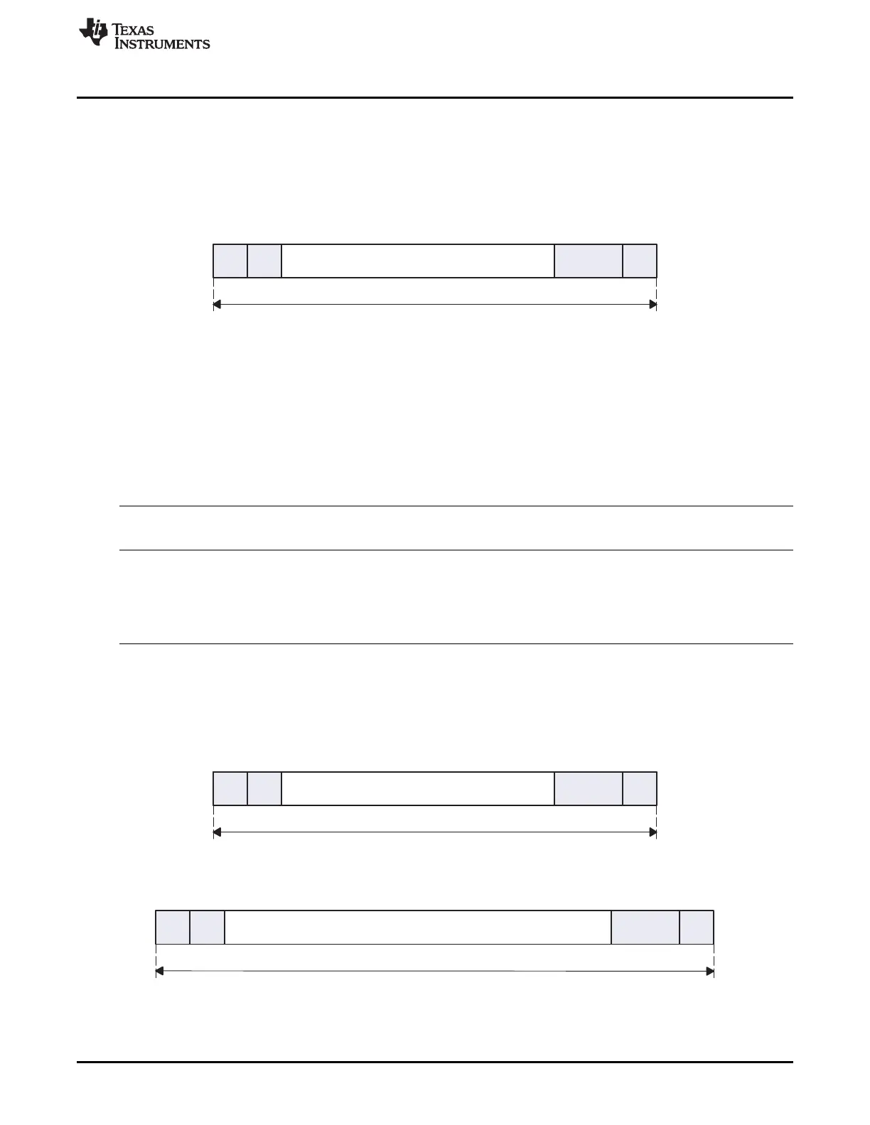
18.3.1.2.2 Data Format
Coding Scheme for Command Token
Command packets always start with 0 and end with 1. The second bit is a transmitter bit1 for a host
command. The content is the command index (coded by 6 bits) and an argument (for example, an
address), coded by 32 bits. The content is protected by 7-bit CRC checksum (see Figure 18-10).
Figure 18-10. Command Token Format
Coding Scheme for Response Token
Response packets always start with 0 and end with a 1. The second bit is a transmitter bit0 for a card
response. The content is different for each type of response (R1, R2, R3, R4, R5, and R6) and the content
is protected by 7-bit CRC checksum. Depending on the type of commands sent to the card, the SD_CMD
register must be configured differently to avoid false CRC or index errors to be flagged on command
response (see Table 18-8). For more details about response types, see the Multimedia Card System
Specification, the SD Memory Card Specification, or the SDIO Card Specification.
Table 18-8. Response Type Summary
(1)
Response Type Index Check Enable CRC Check Enable
SD_CMD[17:16] SD_CMD[20] SD_CMD[19]
RSP_TYPE CICE CCCE Name of Response Type
00 0 0 No Response
01 0 1 R2
10 0 0 R3 (R4 for SD cards)
10 1 1 R1, R6, R5 (R7 for SD cards)
11 1 1 R1b, R5b
(1)
The MMC/SD/SDIO host controller assumes that both clocks may be switched off, whatever the value set in the
SD_SYSCONFIG[9:8] CLOCKACTIVITY bit.
Figure 18-11 and Figure 18-12 depict the 48-bit and 136-bit response packets.
Figure 18-11. 48-Bit Response Packet (R1, R3, R4, R5, R6)
Figure 18-12. 136-Bit Response Packet (R2)
3355
SPRUH73H–October 2011–Revised April 2013 Multimedia Card (MMC)
Submit Documentation Feedback
Copyright © 2011–2013, Texas Instruments Incorporated

 Loading...


