Enhanced PWM (ePWM) Module
www.ti.com
15.2.4.5.4 Trip-Zone Flag Register (TZFLG)
The trip-zone flag register (TZFLG) is shown in Figure 15-88 and described in Table 15-82.
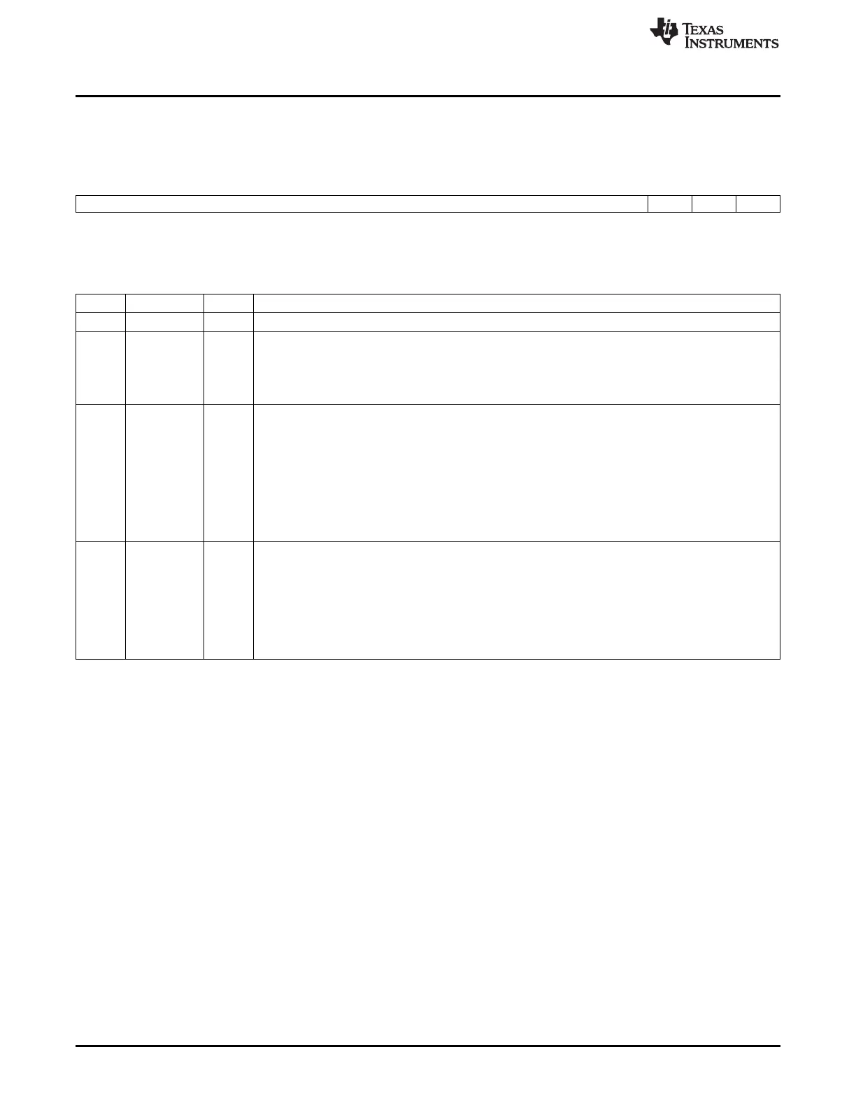
Figure 15-88. Trip-Zone Flag Register (TZFLG)
15 3 2 1 0
Reserved OST CBC INT
R-0 R-0 R-0 R-0
LEGEND: R/W = Read/Write; R = Read only; -n = value after reset
Table 15-82. Trip-Zone Flag Register (TZFLG) Field Descriptions
Bits Name Value Description
15-3 Reserved 0 Reserved
2 OST Latched Status Flag for A One-Shot Trip Event.
0 No one-shot trip event has occurred.
1 Indicates a trip event has occurred on a pin selected as a one-shot trip source.
This bit is cleared by writing the appropriate value to the TZCLR register (Section 15.2.4.5.5).
1 CBC Latched Status Flag for Cycle-By-Cycle Trip Event
0 No cycle-by-cycle trip event has occurred.
1 Indicates a trip event has occurred on a pin selected as a cycle-by-cycle trip source. The TZFLG[CBC]
bit will remain set until it is manually cleared by the user. If the cycle-by-cycle trip event is still present
when the CBC bit is cleared, then CBC will be immediately set again. The specified condition on the
pins is automatically cleared when the ePWM time-base counter reaches zero (TBCNT = 0000h) if the
trip condition is no longer present. The condition on the pins is only cleared when the TBCNT = 0000h
no matter where in the cycle the CBC flag is cleared.
This bit is cleared by writing the appropriate value to the TZCLR register (Section 15.2.4.5.5).
0 INT Latched Trip Interrupt Status Flag
0 Indicates no interrupt has been generated.
1 Indicates an EPWMxTZINT interrupt was generated because of a trip condition.
No further EPWMxTZINT interrupts will be generated until this flag is cleared. If the interrupt flag is
cleared when either CBC or OST is set, then another interrupt pulse will be generated. Clearing all flag
bits will prevent further interrupts.
This bit is cleared by writing the appropriate value to the TZCLR register (Section 15.2.4.5.5).
1598
Pulse-Width Modulation Subsystem (PWMSS) SPRUH73H–October 2011–Revised April 2013
Submit Documentation Feedback
Copyright © 2011–2013, Texas Instruments Incorporated

 Loading...


