www.ti.com
ARM Cortex-A8 MPU Subsystem
3.1.4.2.3 ARM Core Supported Features
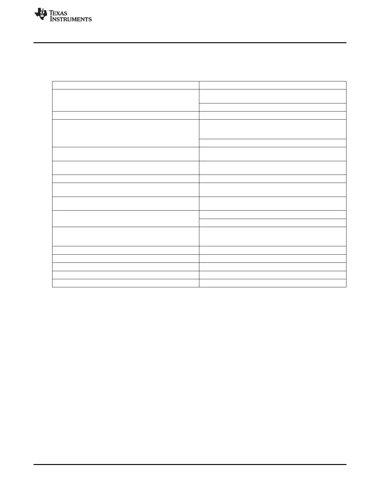
Table 3-3 provides a list of main functions of the Cortex™-A8 core supported inside the MPU Subsystem.
Table 3-3. ARM Core Supported Features
Features Comments
ARM version 7 ISA Standard ARM instruction set + Thumb2™, JazelleX™ Java
accelerator, and Media extensions.
Backward compatible with previous ARM ISA versions.
L1 Icache and Dcache 32 KB , 4-way, 16 word line, 128 bit interface.
L2 Cache 256 KB, 8-way, 16 word line, 128 bit interface to L1, ECC/Parity
is supported. The L2 cache and cache controller are embedded
within the ARM core.
L2 valid bits cleared by software loop or by hardware.
TLB Fully associative and separate ITLB with 32 entries and DTLB
with 32 entries.
CoreSight ETM The CoreSight ETM is embedded with the ARM core. The 32KB
buffer (ETB) exists at the Chip Level (DebugSS)
Branch Target Address Cache 512 entries
Enhanced Memory Management Unit Mapping sizes are 4KB, 64KB, 1MB, and 16MB. (ARM MMU
adds extended physical address ranges)
Neon Gives greatly enhanced throughput for media workloads and
VFP-Lite support.
Flat Memories 176 Kbytes of ROM
64 Kbytes of RAM
Buses 128 bit AXI internal bus from CortexA8 routed by an AXI2OCP
bridge to the interrupt controller, ROM, RAM, and 3
asynchronous OCP bridges (128 bits, and 64 bits)
Low interrupt latency Closely coupled INTC to the ARM core with 128 interrupt lines
Vectored Interrupt Controller Port Present.
JTAG based debug Supported via DAP
Trace support Supported via TPIU
External Coprocessor Not supported
3.1.5 Interrupt Controller
The Host ARM Interrupt Controller (AINTC) is responsible for prioritizing all service requests from the
system peripherals and generating either nIRQ or nFIQ to the host. The type of the interrupt (nIRQ or
nFIQ) and the priority of the interrupt inputs are programmable. The AINTC interfaces to the ARM
processor via the AXI port through an AXI2OCP bridge and runs at half the processor speed. It has the
capability to handle up to 128 requests which can be steered/prioritized as A8 nFIQ or nIRQ interrupt
requests.
The general features of the AINTC are:
• Up to 128 level sensitive interrupts inputs
• Individual priority for each interrupt input
• Each interrupt can be steered to nFIQ or nIRQ
• Independent priority sorting for nFIQ and nIRQ
3.1.6 Power Management
3.1.6.1 Power Domains
The MPU subsystem is divided into 5 power domains controlled by the PRCM, as shown in Figure
Figure 3-5.
171
SPRUH73H–October 2011–Revised April 2013 ARM MPU Subsystem
Submit Documentation Feedback
Copyright © 2011–2013, Texas Instruments Incorporated

 Loading...


