Functional Description
www.ti.com
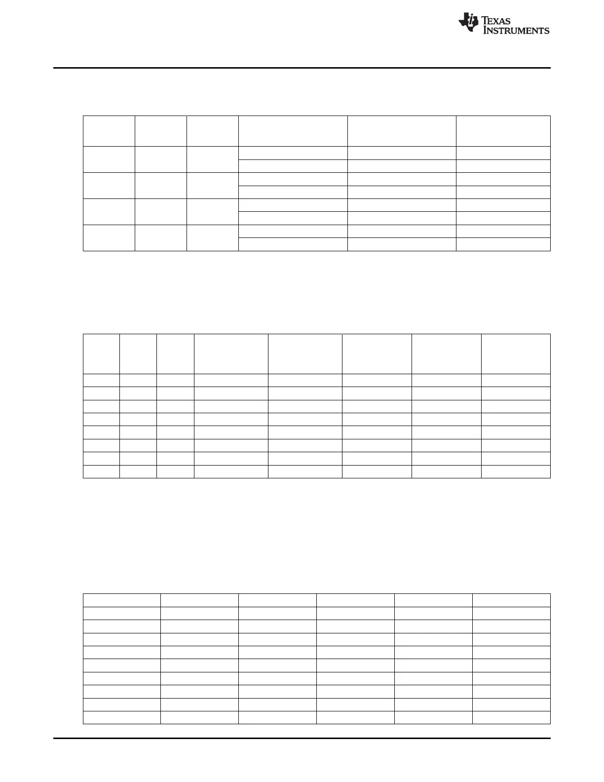
9.2.5 DDR PHY
Table 9-7. DDR Slew Rate Control Settings
(1)(2)
Turn-on Time for Drv8 Max Noise on IO
Turn-on
sr0 sr1 Interface Setting Supply for Drv8 Setting
Time Level
(ps)
(3)
(4)
1.5 V 117 0.43
0 0 Fastest
1.8 V 116 0.6
1.5 V 430 0.17
0 1 Fast
1.8 V 443 0.24
1.5 V 530 0.15
1 0 Slow
1.8 V 567 0.21
1.5 V 790 0.13
1 1 Slowest
1.8 V 815 0.18
(1)
These values are programmed in the following registers: ddr_cmd0_ioctrl, ddr_cmd1_ioctrl, ddr_cmd2_ioctrl, ddr_data0_ioctrl,
ddr_data1_ioctrl.
(2)
Values for DDR_CMDx_IOCTRL.io_config_sr_clk should be programmed to the same value.
(3)
Value is obtained at nominal PTV.
(4)
Value is the average across PTVs.
Table 9-8. DDR Impedance Control Settings
(1)(2)(3)
Example:
Output Example:
Drive Setting Drive Strength |I
OH
|, |I
OL
| for R
ext
I2 I1 I0 Impedance R
on
for R
ext
=
Name |I
OH
|, |I
OL
| =
(R
on
) 49.9 ohms
49.9 ohms
0 0 0 Drv5 1.6*R
ext
0.625*I
out
80 ohms 5 mA
0 0 1 Drv6 1.33*R
ext
0.75*I
out
67 ohms 6 mA
0 1 0 Drv7 1.14*R
ext
0.875*I
out
57 ohms 7 mA
0 1 1 Drv8 R
ext
I
out
50 ohms 8 mA
1 0 0 Drv9 0.88*R
ext
1.125*I
out
44 ohms 9 mA
1 0 1 Drv10 0.8*R
ext
1.250*I
out
40 ohms 10 mA
1 1 0 Drv11 0.73*R
ext
1.375*I
out
36 ohms 11 mA
1 1 1 Drv12 0.67*R
ext
1.5*I
out
33 ohms 12 mA
(1)
These values are programmed in the following registers: ddr_cmd0_ioctrl, ddr_cmd1_ioctrl, ddr_cmd2_ioctrl, ddr_data0_ioctrl,
ddr_data1_ioctrl.
(2)
Values for DDR_CMDx_IOCTRL.io_config_i_clk should be programmed to the same value.
(3)
R
ext
is the external VTP compensation resistor connected to DDR_VTP terminal.
9.2.5.1 DDR PHY to IO Pin Mapping
The following table describes the DDR PHY to IO pin mapping.
Table 9-9. DDR PHY to IO Pin Mapping
Macro Pin CMD0 CMD1 CMD2 DATA0 DATA1
0 ddr_ba2 Unconn ddr_cke ddr_d8 ddr_d0
1 ddr_wen ddr_a15 ddr_resetn ddr_d9 ddr_d1
2 ddr_ba0 ddr_a2 ddr_odt ddr_d10 ddr_d2
3 ddr_a5 ddr_a12 Unconn ddr_d11 ddr_d3
4 ddr_ck ddr_a7 ddr_a14 ddr_d12 ddr_d4
5 ddr_ckn ddr_ba1 ddr_a13 ddr_d13 ddr_d5
6 ddr_a3 ddr_a10 ddr_csn0 ddr_d14 ddr_d6
7 ddr_a4 ddr_a0 Unconn ddr_d15 ddr_d7
8 ddr_a8 ddr_a11 ddr_a1 ddr_dqm1 ddr_dqm0
756
Control Module SPRUH73H–October 2011–Revised April 2013
Submit Documentation Feedback
Copyright © 2011–2013, Texas Instruments Incorporated

 Loading...


