www.ti.com
UART Registers
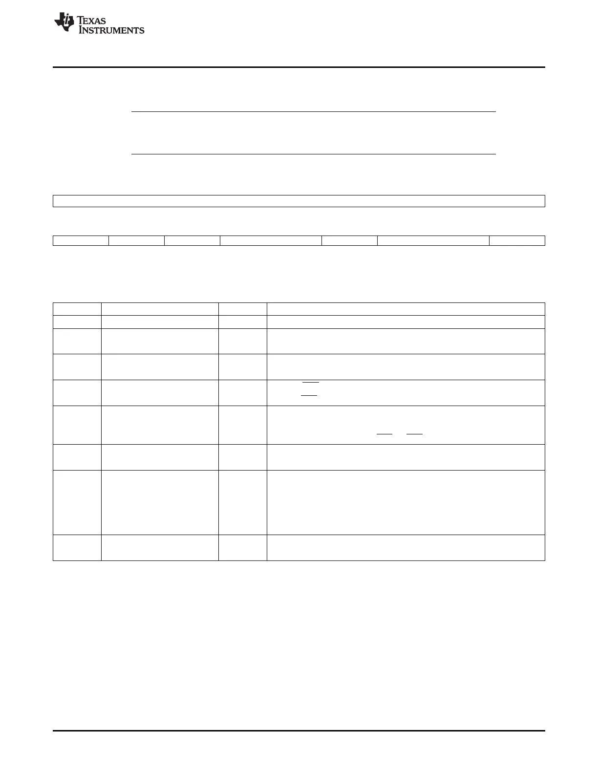
19.5.1.27 Supplementary Control Register (SCR)
The supplementary control register (SCR) is shown in Figure 19-60 and described in Table 19-58.
NOTE: Bit 4 enables the wake-up interrupt, but this interrupt is not mapped into the IIR register.
Therefore, when an interrupt occurs and there is no interrupt pending in the IIR register, the
SSR[1] bit must be checked. To clear the wake-up interrupt, bit SCR[4] must be reset to 0.
Figure 19-60. Supplementary Control Register (SCR)
15 8
Reserved
R-0
7 6 5 4 3 2 1 0
RXTRIGGRANU1 TXTRIGGRANU1 DSRIT RXCTSDSRWAKEUPENABLE TXEMPTYCTLIT DMAMODE2 DMAMODECTL
R/W-0 R/W-0 R/W-0 R/W-0 R/W-0 R/W-0 R/W-0
LEGEND: R/W = Read/Write; R = Read only; -n = value after reset
Table 19-58. Supplementary Control Register (SCR) Field Descriptions
Bit Field Value Description
15-8 Reserved 0 Reserved.
7 RXTRIGGRANU1 0 Disables the granularity of 1 for trigger RX level.
1 Enables the granularity of 1 for trigger RX level.
6 TXTRIGGRANU1 0 Disables the granularity of 1 for trigger TX level.
1 Enables the granularity of 1 for trigger TX level.
5 DSRIT 0 Disables DSR interrupt.
1 Enables DSR interrupt.
4 RXCTSDSRWAKEUPENABLE RX CTS wake-up enable.
0 Disables the WAKE UP interrupt and clears SSR[1].
1 Waits for a falling edge of RX, CTS, or DSR pins to generate an interrupt.
3 TXEMPTYCTLIT 0 Normal mode for THR interrupt.
1 THR interrupt is generated when TX FIFO and TX shift register are empty.
2-1 DMAMODE2 0-3h Specifies the DMA mode valid if SCR[0] = 1:
0 DMA mode 0 (no DMA).
1h DMA mode 1 (UARTnDMAREQ[0] in TX, UARTnDMAREQ[1] in RX)
2h DMA mode 2 (UARTnDMAREQ[0] in RX)
3h DMA mode 3 (UARTnDMAREQ[0] in TX)
0 DMAMODECTL 0 The DMAMODE is set with FCR[3].
1 The DMAMODE is set with SCR[2:1].
3529
SPRUH73H–October 2011–Revised April 2013 Universal Asynchronous Receiver/Transmitter (UART)
Submit Documentation Feedback
Copyright © 2011–2013, Texas Instruments Incorporated

 Loading...


