UART Registers
www.ti.com
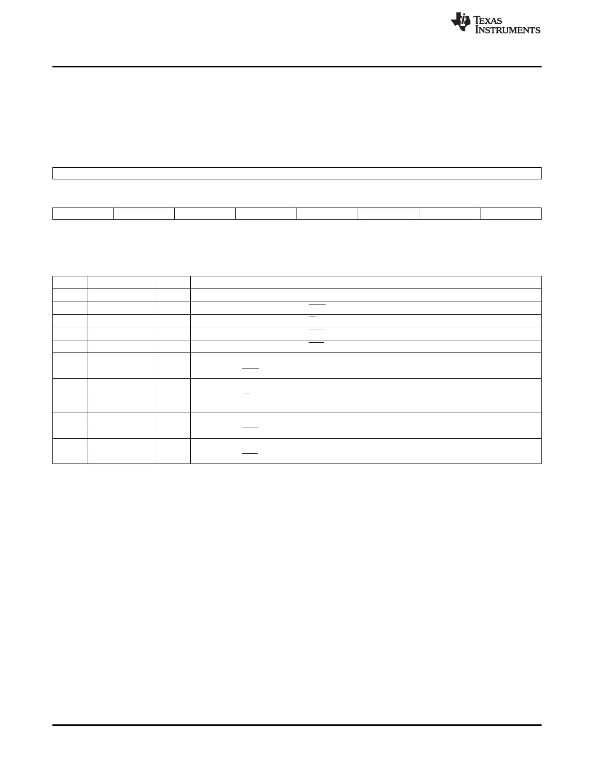
19.5.1.15 Modem Status Register (MSR)
The modem status register (MSR) provides information about the current state of the control lines from the
modem, data set, or peripheral device to the Local Host. It also indicates when a control input from the
modem changes state. The modem status register (MSR) is shown in Figure 19-48 and described in
Table 19-44.
Figure 19-48. Modem Status Register (MSR)
15 8
Reserved
R-0
7 6 5 4 3 2 1 0
NCD_STS NRI_STS NDSR_STS NCTS_STS DCD_STS RI_STS DSR_STS CTS_STS
R-unknown R-unknown R-unknown R-unknown R-0 R-0 R-0 R-0
LEGEND: R/W = Read/Write; R = Read only; -n = value after reset
Table 19-44. Modem Status Register (MSR) Field Descriptions
Bit Field Value Description
15-8 Reserved 0 Reserved.
7 NCD_STS This bit is the complement of the DCD input. In loopback mode, it is equivalent to MCR[3].
6 NRI_STS This bit is the complement of the RI input. In loopback mode, it is equivalent to MCR[2].
5 NDSR_STS This bit is the complement of the DSR input. In loopback mode, it is equivalent to MCR[0].
4 NCTS_STS This bit is the complement of the CTS input. In loopback mode, it is equivalent to MCR[1].
3 DCD_STS 0 No change.
1 Indicates that DCD input (or MCR[3] in loopback mode) has changed. Cleared on a read.
2 RI_STS 0 No change.
1 Indicates that RI input (or MCR[2] in loopback mode) changed state from low to high. Cleared on a
read.
1 DSR_STS 0 No change.
1 Indicates that DSR input (or MCR[0] in loopback mode) changed state. Cleared on a read.
0 CTS_STS 0 No change.
1 Indicates that CTS input (or MCR[1] in loopback mode) changed state. Cleared on a read.
3520
Universal Asynchronous Receiver/Transmitter (UART) SPRUH73H–October 2011–Revised April 2013
Submit Documentation Feedback
Copyright © 2011–2013, Texas Instruments Incorporated

 Loading...


