Trig Register
(TTGR)
0x0000 0000
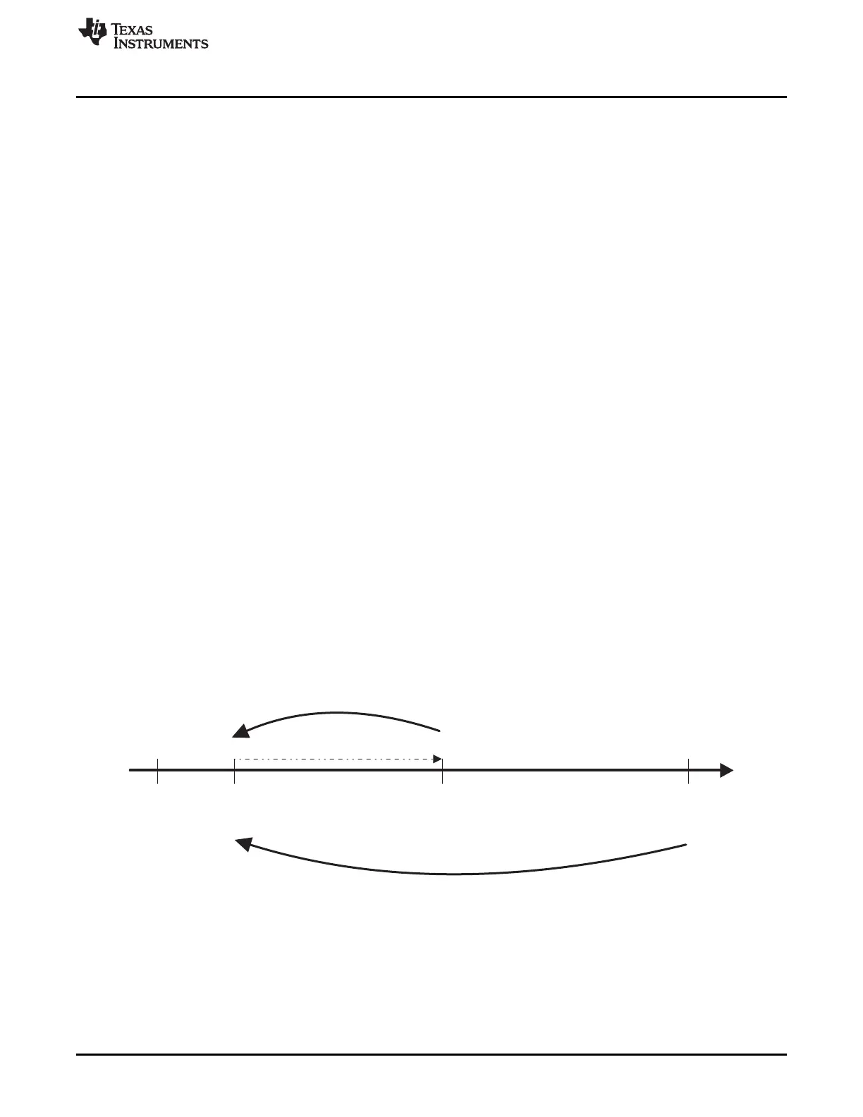
Load register
(TLDR)
Counter register
(TCRR)
Overflow
pulse is generated
Auto-reload on
(TCLR (AR) = 1)
0xFFFF FFFF
www.ti.com
DMTimer
20.1.3 Functional Description
20.1.3.1 Functional Description
The general-purpose timer is an upward counter. It supports 3 functional modes:
• Timer mode
• Capture mode
• Compare mode
By default, after core reset, the capture and compare modes are disabled.
20.1.3.1.1 Timer Mode Functionality
The timer is an upward counter that can be started and stopped at any time through the Timer Control
Register (TCLR ST bit). The Timer Counter Register (TCRR) can be loaded when stopped or on the fly
(while counting). TCRR can be loaded directly by a TCRR Write access with the new timer value. TCRR
can also be loaded with the value held in the Timer Load Register TLDR by a trigger register (TTGR)
Write access. The TCRR loading is done regardless the TTGR written value. The timer counter register
TCRR value can be read when stopped or captured on the fly by a TCRR Read access. The timer is
stopped and the counter value is cleared to “0” when the module’s reset is asserted. The timer is
maintained in stop after reset is released. When the timer is stopped TCRR is frozen and it can be
restarted from the frozen value unless TCRR has been reloaded with a new value.
In the one shot mode (TCLR AR bit = 0), the counter is stopped after counting overflow (counter value
remains at zero).
When the auto-reload mode is enabled (TCLR AR bit = 1), the TCRR is reloaded with the Timer Load
Register (TLDR) value after a counting overflow.
It is not recommended to put the overflow value (FFFF FFFFh) in TLDR because it can lead to undesired
results.
An interrupt can be issued on overflow if the overflow interrupt enable bit is set in the timer Interrupt
Enable Register (IRQENABLE_SET OVF_IT_FLAG bit = 1). A dedicated output pin (PORTIMERPWM) is
programmed through TCLR (TRG and PT bits) to generate one positive pulse (prescaler duration) or to
invert the current value (toggle mode) when an overflow occurs.
Figure 20-4. TCRR Timing Value
20.1.3.1.2 Capture Mode Functionality
The timer value in TCRR can be captured and saved in TCAR1 or TCAR2 function of the mode selected
in TCLR through the field CAPT_MODE when a transition is detected on the module input pin
(PIEVENTCAPT). The edge detection circuitry monitors transitions on the input pin (PIEVENTCAPT).
3557
SPRUH73H–October 2011–Revised April 2013 Timers
Submit Documentation Feedback
Copyright © 2011–2013, Texas Instruments Incorporated

 Loading...


