Enhanced PWM (ePWM) Module
www.ti.com
15.2.4.7 PWM-Chopper Submodule Register
The PWM-chopper control register (PCCTL) is shown in Figure 15-96 and described in Table 15-91.
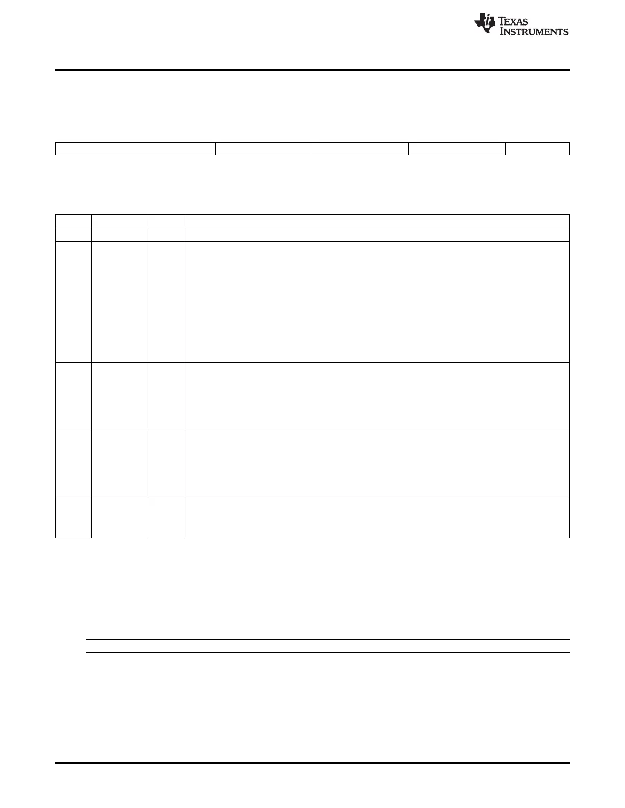
Figure 15-96. PWM-Chopper Control Register (PCCTL)
15 11 10 8 7 5 4 1 0
Reserved CHPDUTY CHPFREQ OSHTWTH CHPEN
R-0 R/W-0 R/W-0 R/W-0 R/W-0
LEGEND: R/W = Read/Write; R = Read only; -n = value after reset
Table 15-91. PWM-Chopper Control Register (PCCTL) Bit Descriptions
Bits Name Value Description
15-11 Reserved 0 Reserved
10-8 CHPDUTY 0-7h Chopping Clock Duty Cycle
0 Duty = 1/8 (12.5%)
1h Duty = 2/8 (25.0%)
2h Duty = 3/8 (37.5%)
3h Duty = 4/8 (50.0%)
4h Duty = 5/8 (62.5%)
5h Duty = 6/8 (75.0%)
6h Duty = 7/8 (87.5%)
7h Reserved
7-5 CHPFREQ 0-7h Chopping Clock Frequency
0 Divide by 1 (no prescale)
1h Divide by 2
2h Divide by 3
3h-7h Divide by 4 to divide by 8
4-1 OSHTWTH 0-Fh One-Shot Pulse Width
0 1 × SYSCLKOUT/8 wide
1h 2 × SYSCLKOUT/8 wide
2h 3 × SYSCLKOUT/8 wide
3h-Fh 4 × SYSCLKOUT/8 wide to 16 × SYSCLKOUT/8 wide
0 CHPEN PWM-chopping Enable
0 Disable (bypass) PWM chopping function
1 Enable chopping function
15.2.4.8 High-Resolution PWM Submodule Registers
Table 15-92 lists the memory-mapped registers for the high-resolution PWM submodule. All other register
offset addresses not listed in Table 15-92 should be considered as reserved locations and the register
contents should not be modified.
Table 15-92. High-Resolution PWM Submodule Registers
Offset Acronym Register Description Section
4h TBPHSHR Time-Base Phase High-Resolution Register Section 15.2.4.8.1
10h CMPAHR Counter-Compare A High-Resolution Register Section 15.2.4.8.2
40h HRCTL HRPWM Control Register Section 15.2.4.8.3
1604
Pulse-Width Modulation Subsystem (PWMSS) SPRUH73H–October 2011–Revised April 2013
Submit Documentation Feedback
Copyright © 2011–2013, Texas Instruments Incorporated

 Loading...


