USB Registers
www.ti.com
16.5.4.6 PWR_CNTL Register (offset = 18h) [reset = 400000h]
PWR_CNTL is shown in Figure 16-139 and described in Table 16-150.
has all the power control bits
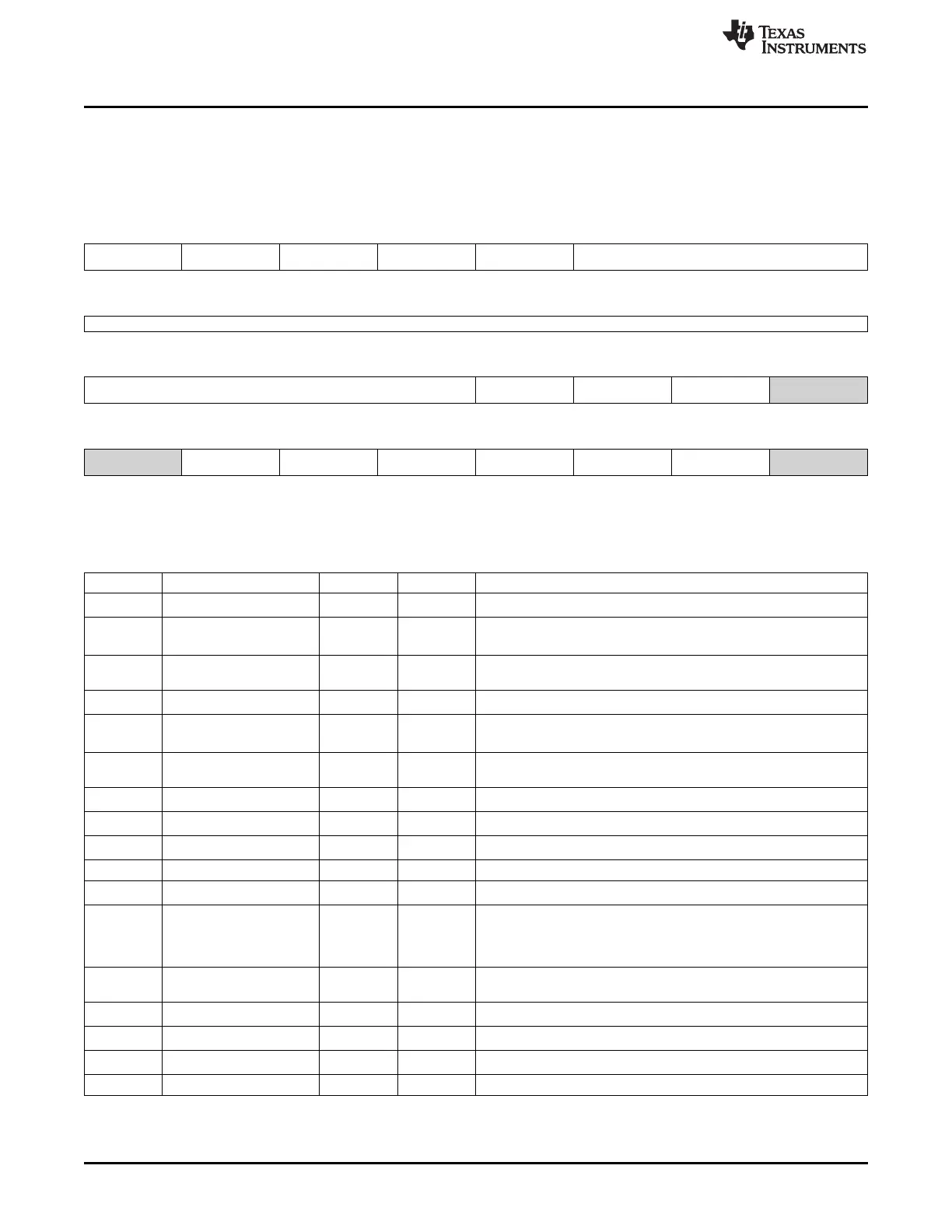
Figure 16-139. PWR_CNTL Register
31 30 29 28 27 26 25 24
RESETDONETCLK RESET_DONE_VMAI VMAIN_GLOBAL_RE RESETDONEMCLK RESETDONE_CHGD LDOPWRCOUNTER
N SET_DONE ET
R-0h R-0h R-0h R-0h R-0h R/W-400h
23 22 21 20 19 18 17 16
LDOPWRCOUNTER
R/W-400h
15 14 13 12 11 10 9 8
LDOPWRCOUNTER FORCEPLLSLOWCL FORCELDOON FORCEPLLON Reserved
K
R/W-400h R/W-0h R/W-0h R/W-0h R/W-0h
7 6 5 4 3 2 1 0
Reserved PLLLOCK USEPLLLOCK USE_DATAPOLARIT DATAPOLARITYN USE_PD_REG PD Reserved
YN_REG
R/W-0h R-0h R/W-0h R/W-0h R/W-0h R/W-0h R/W-0h R/W-0h
LEGEND: R/W = Read/Write; R = Read only; W1toCl = Write 1 to clear bit; -n = value after reset
Table 16-150. PWR_CNTL Register Field Descriptions
Bit Field Type Reset Description
31 RESETDONETCLK R 0h
Goes high when the RESET is synchronized to TCLK
30 RESET_DONE_VMAIN R 0h
Goes high when LDO domain is up and PLL LOCK is available and
utmi_reset is de-asserted.
29 VMAIN_GLOBAL_RESET R 0h
Goes high when LDO domain is up and PLL LOCK is available.
_DONE
28 RESETDONEMCLK R 0h
Goes high when the RESET is synchronized to MCLK
27 RESETDONE_CHGDET R 0h
Goes high when the RESET is synchronized to charger detect
oscillator clock domain
26-12 LDOPWRCOUNTER R/W 400h This is the value of the counter used for LDO power up.
RESET to default.
11 FORCEPLLSLOWCLK R/W 0h
Forces the PLL to the slow clk mode
10 FORCELDOON R/W 0h
Forces the LDO to be ON.
9 FORCEPLLON R/W 0h
Forces the PLL to be ON.
8-7 Reserved R/W 0h
6 PLLLOCK R 0h
Lock signal from the PLL
5 USEPLLLOCK R/W 0h This signal is used to indicate to the Phy, not to do any clock related
activity until PLLLOCK = 1 .This is not the default option.0 do not
use PLLLOCK.
1 use PLLLOCK as a clock gate.
4 USE_DATAPOLARITYN_ R/W 0h 1 -andgt
REG use bit 3 as override for the DATAPOLARITYN signal.
3 DATAPOLARITYN R/W 0h
Override value of datapolarityn
2 USE_PD_REG R/W 0h
Use bit 1 from this register as PD override when set to '1'
1 PD R/W 0h
Override value for PD
0 Reserved R/W 0h
1910
Universal Serial Bus (USB) SPRUH73H–October 2011–Revised April 2013
Submit Documentation Feedback
Copyright © 2011–2013, Texas Instruments Incorporated

 Loading...


