UART Registers
www.ti.com
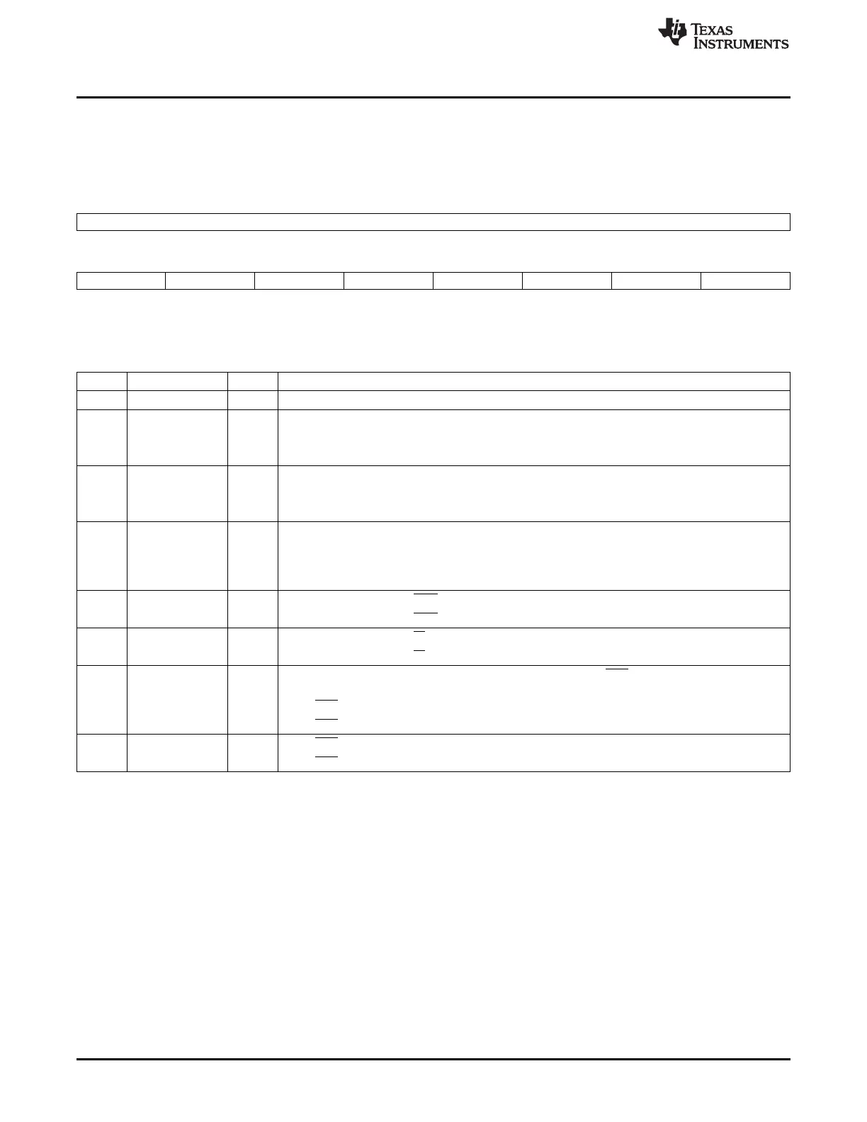
19.5.1.11 Modem Control Register (MCR)
Bits 3-0 control the interface with the modem, data set, or peripheral device that is emulating the modem.
The modem control register (MCR) is shown in Figure 19-44 and described in Table 19-40.
Figure 19-44. Modem Control Register (MCR)
15 8
Reserved
R-0
7 6 5 4 3 2 1 0
Reserved TCRTLR XONEN LOOPBACKEN CDSTSCH RISTSCH RTS DTR
R-0 R/W-0 R/W-0 R/W-0 R/W-0 R/W-0 R/W-0 R/W-0
LEGEND: R/W = Read/Write; R = Read only; -n = value after reset
Table 19-40. Modem Control Register (MCR) Field Descriptions
Bit Field Value Description
15-7 Reserved 0 Reserved.
6 TCRTLR Can be written only when EFR[4] = 1.
0 No action.
1 Enables access to the TCR and TLR registers.
5 XONEN Can be written only when EFR[4] = 1.
0 Disable XON any function.
1 Enable XON any function.
4 LOOPBACKEN Loopback mode enable.
0 Normal operating mode.
1 Enable local loopback mode (internal). In this mode, the MCR[3:0] signals are looped back into
MSR[7:4]. The transmit output is looped back to the receive input internally.
3 CDSTSCH 0 In loopback mode, forces DCD input high and IRQ outputs to INACTIVE state.
1 In loopback mode, forces DCD input low and IRQ outputs to INACTIVE state.
2 RISTSCH 0 In loopback mode, forces RI input inactive (high).
1 In loopback mode, forces RI input active (low).
1 RTS In loopback mode, controls MSR[4]. If auto-RTS is enabled, the RTS output is controlled by
hardware flow control.
0 Force RTS output to inactive (high).
1 Force RTS output to active (low).
0 DTR 0 Force DTR output (used in loopback mode) to inactive (high).
1 Force DTR output (used in loopback mode) to active (low).
3516
Universal Asynchronous Receiver/Transmitter (UART) SPRUH73H–October 2011–Revised April 2013
Submit Documentation Feedback
Copyright © 2011–2013, Texas Instruments Incorporated

 Loading...


