GPMC
www.ti.com
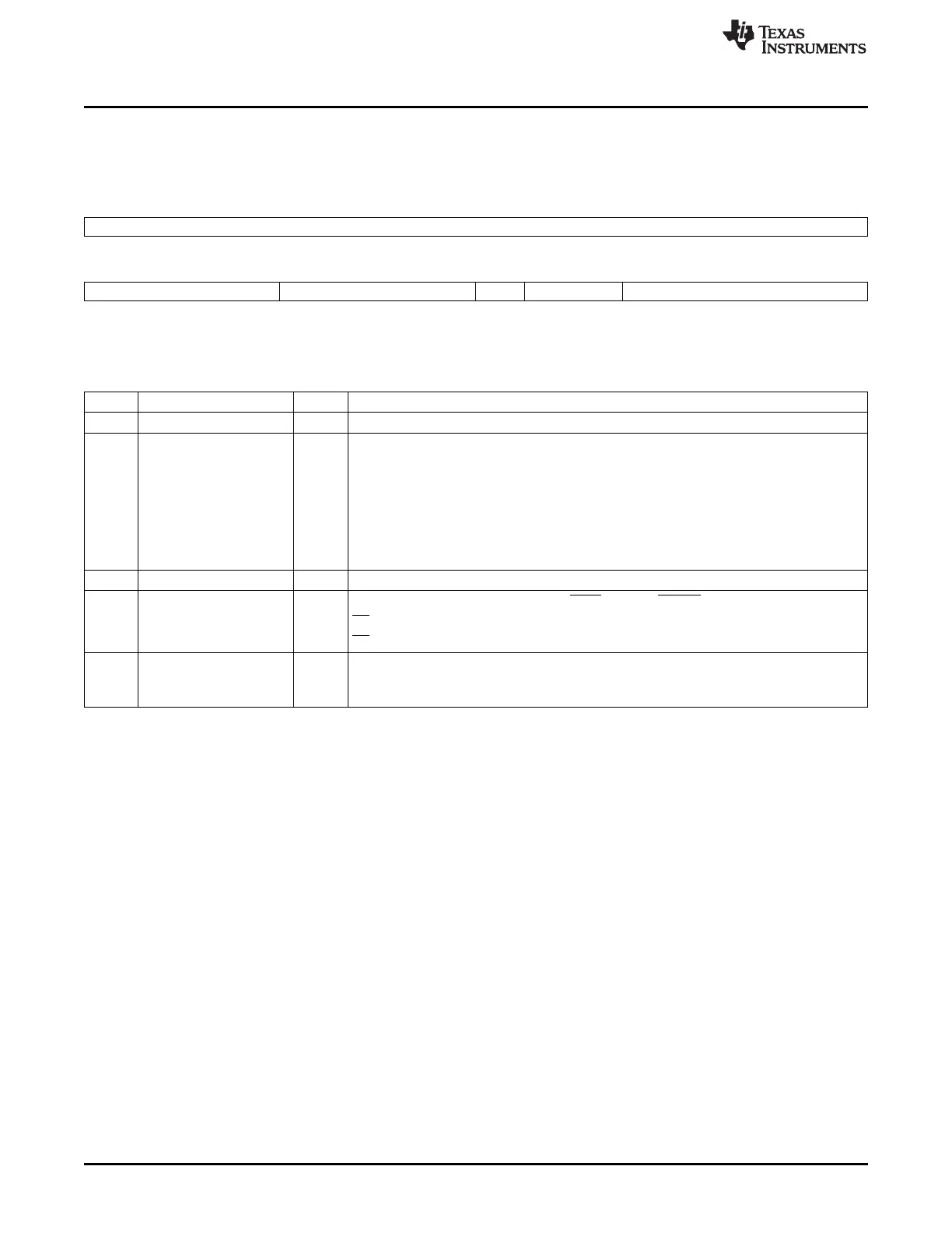
7.1.5.17 GPMC_CONFIG7_i
Chip-select address mapping configuration.
Figure 7-67. GPMC_CONFIG7_i
31 16
Reserved
R-0
15 12 11 8 7 6 5 0
Reserved MASKADDRESS Rsvd CSVALID BASEADDRESS
R-0 R/W-0 R-0 R/W-0 R/W-0
LEGEND: R/W = Read/Write; R = Read only; -n = value after reset
Table 7-71. GPMC_CONFIG7_i Field Descriptions
Bit Field Value Description
31-12 Reserved 0 Reserved
11-8 MASKADDRESS Chip-select mask address. Values not listed must be avoided as they create holes in the
chip-select address space.
0 Chip-select size of 256 Mbytes
8h Chip-select size of 128 Mbytes
Ch Chip-select size of 64 Mbytes
Eh Chip-select size of 32 Mbytes
Fh Chip-select size of 16 Mbytes
7 Reserved 0 Reserved
6 CSVALID Chip-select enable (reset value is 1 for CS[0] and 0 for CS[1-5]).
0 CS disabled
1 CS enabled
5-0 BASEADDRESS 0-3Fh Chip-select base address.
CSi base address where i = 0 to 3 (16 Mbytes minimum granularity). Bits [5-0] corresponds
to A29, A28, A27, A26, A25, and A24.
384
Memory Subsystem SPRUH73H–October 2011–Revised April 2013
Submit Documentation Feedback
Copyright © 2011–2013, Texas Instruments Incorporated

 Loading...


