www.ti.com
DMTimer
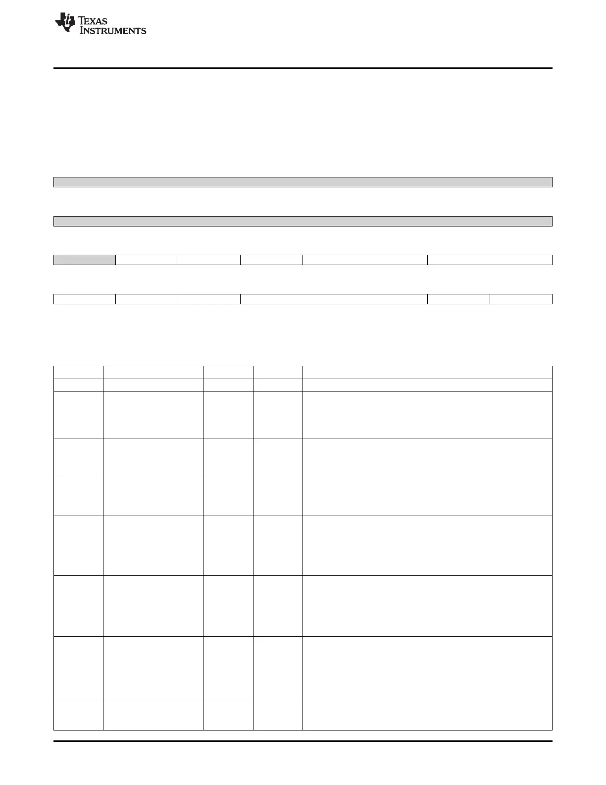
20.1.5.9 TCLR Register (offset = 38h) [reset = 0h]
TCLR is shown in Figure 20-17 and described in Table 20-19.
When the TCM field passed from (00) to any other combination then the TCAR_IT_FLAG and the edge
detection logic are cleared. The ST bit of TCLR register may be updated from the OCP interface or reset
due to one-shot overflow. The OCP interface update has the priority.
Figure 20-17. TCLR Register
31 30 29 28 27 26 25 24
Reserved
R-0h
23 22 21 20 19 18 17 16
Reserved
R-0h
15 14 13 12 11 10 9 8
Reserved GPO_CFG CAPT_MODE PT TRG TCM
R-0h R/W-0h R/W-0h R/W-0h R/W-0h R/W-0h
7 6 5 4 3 2 1 0
SCPWM CE PRE PTV AR ST
R/W-0h R/W-0h R/W-0h R/W-0h R/W-0h R/W-0h
LEGEND: R/W = Read/Write; R = Read only; W1toCl = Write 1 to clear bit; -n = value after reset
Table 20-19. TCLR Register Field Descriptions
Bit Field Type Reset Description
31-15 Reserved R 0h
14 GPO_CFG R/W 0h
General purpose output this register drives directly the
PORGPOCFG output pin
0x0 = PORGPOCFG drives 0
0x1 = PORGPOCFG drives 1
13 CAPT_MODE R/W 0h
Capture mode.
0x0 = Single capture
0x1 = Capture on second event
12 PT R/W 0h
Pulse or toggle mode on PORTIMERPWM output pin
0x0 = Pulse
0x1 = Toggle
11-10 TRG R/W 0h
Trigger output mode on PORTIMERPWM output pin
0x0 = No trigger
0x1 = Trigger on overflow
0x2 = Trigger on overflow and match
0x3 = Reserved
9-8 TCM R/W 0h
Transition Capture Mode on PIEVENTCAPT input pin
0x0 = No capture
0x1 = Capture on low to high transition
0x2 = Capture on high to low transition
0x3 = Capture on both edge transition
7 SCPWM R/W 0h
This bit should be set or clear while the timer is stopped or the
trigger is off
0x0 = Clear the PORTIMERPWM output pin and select positive
pulse for pulse mode
0x1 = Set the PORTIMERPWM output pin and select negative pulse
for pulse mode
6 CE R/W 0h
0x0 = Compare mode is disabled
0x1 = Compare mode is enabled
3575
SPRUH73H–October 2011–Revised April 2013 Timers
Submit Documentation Feedback
Copyright © 2011–2013, Texas Instruments Incorporated

 Loading...


