www.ti.com
Power, Reset, and Clock Management
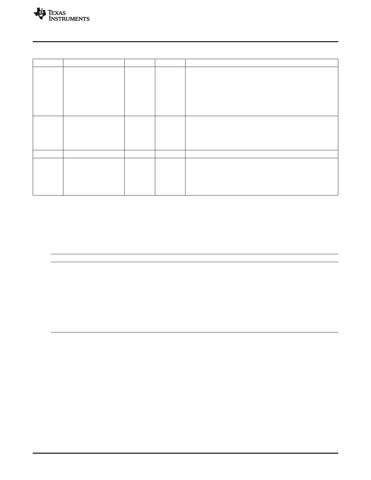
Table 8-187. PM_PER_PWRSTCTRL Register Field Descriptions (continued)
Bit Field Type Reset Description
4 LowPowerStateChange R/W 0h Power state change request when domain has already performed a
sleep transition.
Allows going into deeper low power state without waking up the
power domain.
0x0 = DIS : Do not request a low power state change.
0x1 = EN : Request a low power state change. This bit is
automatically cleared when the power state is effectively changed or
when power state is ON.
3 LogicRETState R/W 1h
Logic state when power domain is RETENTION
0x0 = logic_off : Only retention registers are retained and remaing
logic is off when the domain is in RETENTION state.
0x1 = logic_ret : Whole logic is retained when domain is in
RETENTION state.
2 Reserved R 0h
1-0 PowerState R/W 3h
PER domain power state control
0x0 = OFF
0x1 = RET
0x2 = Reserved
0x3 = ON
8.1.13.3 PRM_WKUP Registers
Table 8-188 lists the memory-mapped registers for the PRM_WKUP. All register offset addresses not
listed in Table 8-188 should be considered as reserved locations and the register contents should not be
modified.
Table 8-188. PRM_WKUP REGISTERS
Offset Acronym Register Name Section
0h RM_WKUP_RSTCTRL This register controls the release of the ALWAYS ON Section 8.1.13.3.1
Domain resets.
4h PM_WKUP_PWRSTCTRL Controls power state of WKUP power domain Section 8.1.13.3.2
8h PM_WKUP_PWRSTST This register provides a status on the current WKUP Section 8.1.13.3.3
power domain state.
[warm reset insensitive]
Ch RM_WKUP_RSTST This register logs the different reset sources of the Section 8.1.13.3.4
ALWON domain.
Each bit is set upon release of the domain reset signal.
Must be cleared by software.
[warm reset insensitive]
715
SPRUH73H–October 2011–Revised April 2013 Power, Reset, and Clock Management (PRCM)
Submit Documentation Feedback
Copyright © 2011–2013, Texas Instruments Incorporated

 Loading...


