UART Registers
www.ti.com
19.5.1.20 Mode Definition Register 2 (MDR2)
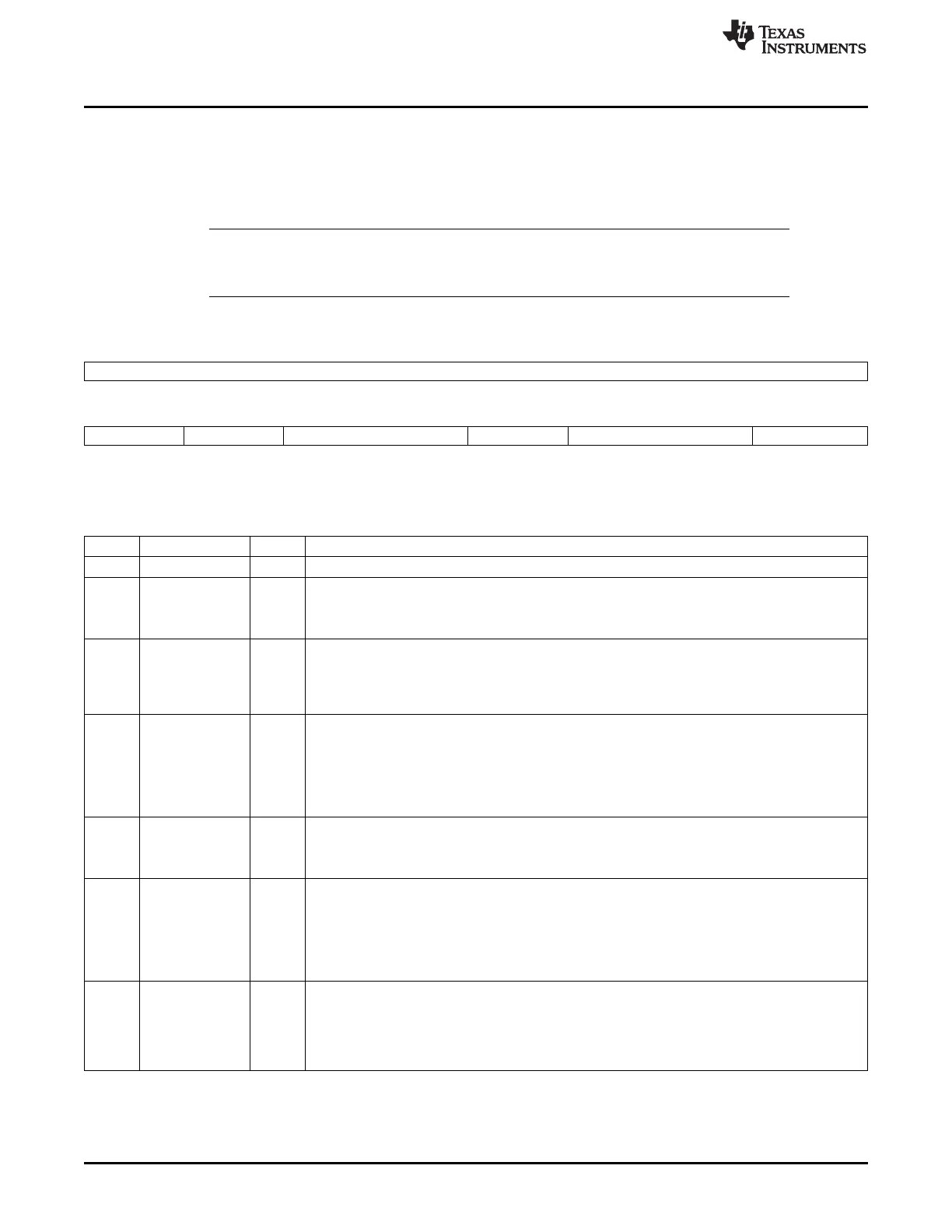
The MDR2[0] bit describes the status of the TX status interrupt in IIR[5]. The IRTXUNDERRUN bit must
be read after a TX status interrupt occurs. The MDR2[2:1] bits set the trigger level for the frame status
FIFO (8 entries) and must be programmed before the mode is programmed in MDR1[2:0]. The mode
definition register 2 (MDR2) is shown in Figure 19-53 and described in Table 19-51.
NOTE: The MDR2[6] bit gives the flexibility to invert the RX pin inside the UART module to ensure
that the protocol at the input of the transceiver module has the same polarity at module level.
By default, the RX pin is inverted because most of transceiver invert the IR receive pin.
Figure 19-53. Mode Definition Register 2 (MDR2)
15 8
Reserved
R-0
7 6 5 4 3 2 1 0
SETTXIRALT IRRXINVERT CIRPULSEMODE UARTPULSE STSFIFOTRIG IRTXUNDERRUN
R/W-0 R/W-0 R/W-0 R/W-0 R/W-0 R-0
LEGEND: R/W = Read/Write; R = Read only; -n = value after reset
Table 19-51. Mode Definition Register 2 (MDR2) Field Descriptions
Bit Field Value Description
15-8 Reserved 0 Reserved.
7 SETTXIRALT Provides alternate functionality for MDR1[4].
0 Normal mode
1 Alternate mode for SETTXIR
6 IRRXINVERT Only for IR mode (IrDA and CIR). Invert RX pin in the module before the voting or sampling system
logic of the infrared block. This does not affect the RX path in UART modem modes.
0 Inversion is performed.
1 No inversion is performed.
5-4 CIRPULSEMODE 0-3h CIR pulse modulation definition. Defines high level of the pulse width associated with a digit:
0 Pulse width of 3 from 12 cycles.
1h Pulse width of 4 from 12 cycles.
2h Pulse width of 5 from 12 cycles.
3h Pulse width of 6 from 12 cycles.
3 UARTPULSE UART mode only. Used to allow pulse shaping in UART mode.
0 Normal UART mode.
1 UART mode with pulse shaping.
2-1 STSFIFOTRIG 0-3h Only for IrDA mode. Frame status FIFO threshold select:
0 1 entry
1h 4 entries
2h 7 entries
3h 8 entries
0 IRTXUNDERRUN IrDA transmission status interrupt. When the TX status interrupt (IIR[5]) occurs, the meaning of the
interrupt is:
0 The last bit of the frame was transmitted successfully without error.
1 An underrun occurred. The last bit of the frame was transmitted but with an underrun error. The bit
is reset to 0 when the RESUME register is read.
3524
Universal Asynchronous Receiver/Transmitter (UART) SPRUH73H–October 2011–Revised April 2013
Submit Documentation Feedback
Copyright © 2011–2013, Texas Instruments Incorporated

 Loading...


