www.ti.com
Ethernet Subsystem Registers
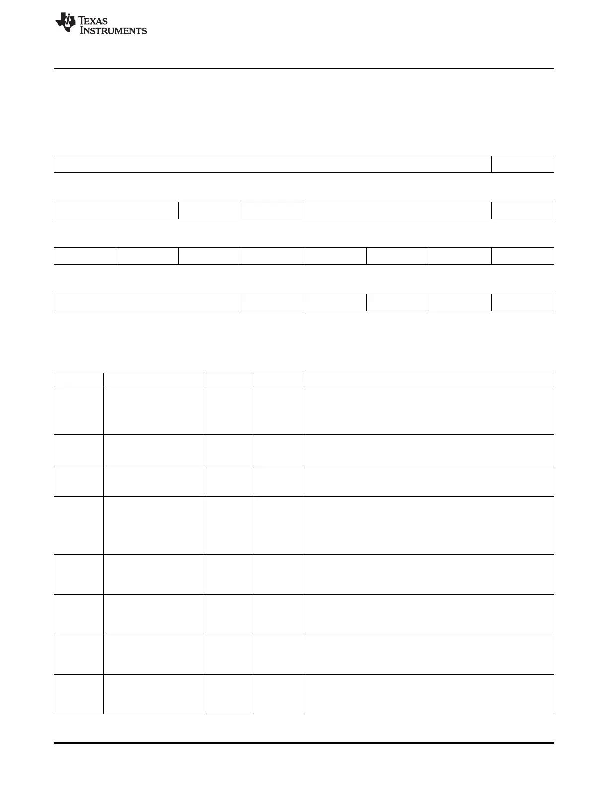
14.5.6.17 P1_CONTROL Register (offset = 100h) [reset = 0h]
P1_CONTROL is shown in Figure 14-137 and described in Table 14-152.
CPSW PORT 1 CONTROL REGISTER
Figure 14-137. P1_CONTROL Register
31 30 29 28 27 26 25 24
Reserved P1_PASS_PRI_TAGG
ED
R/W-0h
23 22 21 20 19 18 17 16
Reserved P1_VLAN_LTYPE2_E P1_VLAN_LTYPE1_E Reserved P1_DSCP_PRI_EN
N N
R/W-0h R/W-0h R/W-0h
15 14 13 12 11 10 9 8
Reserved P1_TS_320 P1_TS_319 P1_TS_132 P1_TS_131 P1_TS_130 P1_TS_129 P1_TS_TTL_NONZE
RO
R/W-0h R/W-0h R/W-0h R/W-0h R/W-0h R/W-0h R/W-0h
7 6 5 4 3 2 1 0
Reserved P1_TS_ANNEX_D_E P1_TS_LTYPE2_EN P1_TS_LTYPE1_EN P1_TS_TX_EN P1_TS_RX_EN
N
R/W-0h R-0h R/W-0h R/W-0h R/W-0h
LEGEND: R/W = Read/Write; R = Read only; W1toCl = Write 1 to clear bit; -n = value after reset
Table 14-152. P1_CONTROL Register Field Descriptions
Bit Field Type Reset Description
24 P1_PASS_PRI_TAGGED R/W 0h Port 1 Pass Priority Tagged
0 - Priority tagged packets have the zero VID replaced with the input
port P1_PORT_VLAN
[11:0]
1 - Priority tagged packets are processed unchanged.
21 P1_VLAN_LTYPE2_EN R/W 0h Port 1 VLAN LTYPE 2 enable
0 - disabled
1 - VLAN LTYPE2 enabled on transmit and receive
20 P1_VLAN_LTYPE1_EN R/W 0h Port 1 VLAN LTYPE 1 enable
0 - disabled
1 - VLAN LTYPE1 enabled on transmit and receive
16 P1_DSCP_PRI_EN R/W 0h Port 1 DSCP Priority Enable
0 - DSCP priority disabled
1 - DSCP priority enabled.
All non-tagged IPV4 packets have their received packet priority
determined by mapping the 6 TOS bits through the port DSCP
priority mapping registers.
14 P1_TS_320 R/W 0h Port 1 Time Sync Destination Port Number 320 enable
0 - disabled
1 - Annex D (UDP/IPv4) time sync packet destination port number
320 (decimal) is enabled.
13 P1_TS_319 R/W 0h Port 1 Time Sync Destination Port Number 319 enable
0 - disabled
1 - Annex D (UDP/IPv4) time sync packet destination port number
319 (decimal) is enabled.
12 P1_TS_132 R/W 0h Port 1 Time Sync Destination IP Address 132 enable
0 - disabled
1 - Annex D (UDP/IPv4) time sync packet destination IP address
number 132 (decimal) is enabled.
11 P1_TS_131 R/W 0h Port 1 Time Sync Destination IP Address 131 enable
0 - disabled
1 - Annex D (UDP/IPv4) time sync packet destination IP address
number 131 (decimal) is enabled.
1373
SPRUH73H–October 2011–Revised April 2013 Ethernet Subsystem
Submit Documentation Feedback
Copyright © 2011–2013, Texas Instruments Incorporated

 Loading...


