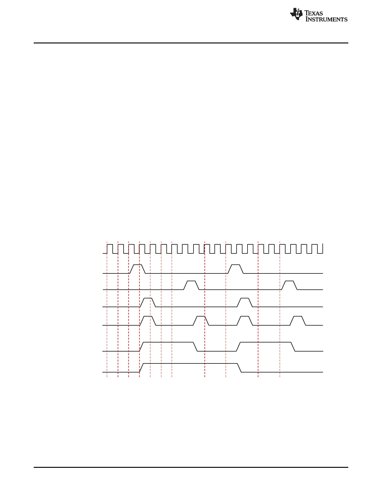
pi_timer_clk
internal
overflow pulse
internal
match pulse
timer_pwm
(TRG=01 & PT=0)
timer_pwm
(TRG=10 & PT=0)
timer_pwm
(TRG=10 & PT=1)
timer_pwm
(TRG=01 & PT=1)
DMTimer
www.ti.com
20.1.3.1.5 Pulse-Width Modulation
The timer can be configured to provide a programmable pulse-width modulation (PORTIMERPWM)
output. The PORTIMERPWM output pin can be configured to toggle on specified event. TCLR (TRG bits)
determines on which register value the PORTIMERPWM pin toggles. Either overflow or match can be
used to toggle the PORTIMERPWM pin, when a compare condition occurs.
In case of overflow and match mode, the match event will be ignored from the moment the mode was set-
up until the first overflow event occurs (see Figure 20-6).
The TCLR (SCPWM bit) can be programmed to set or clear the PORTIMERPWM output signal while the
counter is stopped or the triggering is off only. This allows fixing a deterministic state of the output pin
when modulation is stopped. The modulation is synchronously stopped when TRG bit is cleared and
overflow occurred.
In the following timing diagram, the internal overflow pulse is set each time (FFFF FFFFFh – TLDR + 1)
value is reached, and the internal match pulse is set when the counter reaches TMAR register value.
According to TCLR (TRG and PT bits) programming value, the timer provides pulse or PWM on the output
pin (PORTIMERPWM).
The TLDR and TMAR registers must keep values smaller than the overflow value (FFFF FFFFh) with at
least 2 units. In case the PWM trigger events are both overflow and match, the difference between the
values kept in TMAR register and the value in TLDR must be at least 2 units. When match event is used
the compare mode TCLR (CE) must be set.
In Figure 20-7, TCLR (SCPWM bit) is cleared to 0. In Figure 20-8, TCLR (SCPWM bit) is set to 1.
Figure 20-7. Timing Diagram of Pulse-Width Modulation with SCPWM = 0
3560
Timers SPRUH73H–October 2011–Revised April 2013
Submit Documentation Feedback
Copyright © 2011–2013, Texas Instruments Incorporated

 Loading...


