Level and Edge Interrupt Enable Registers
Interrupt Enable Register 1 or 2
Line(0) Line(i)
Status(0)
Synchronous path
edge and level
detection logic
Interrupt Status Register 1 or 2
GPIO line(0) in input
GPIO line(i) in input
GPIO0–3
Interrupt
request
line 1 or 2
Status(i)
Line(i+1) Line(31)
Status(i+1)
Status(31)
Line(0) Line(i) Line(i+1) Line(31)
www.ti.com
Functional Description
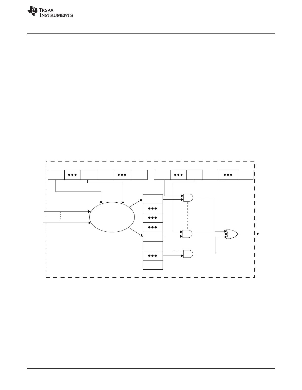
25.3.3.2 Synchronous Path: Interrupt Request Generation
In Active mode, once the GPIO configuration registers have been set to enable the interrupt generation, a
synchronous path (Figure 25-3) samples the transitions and levels on the input GPIO with the internally
gated interface clock. When an event matches the programmed settings, the corresponding bit in the
GPIO_IRQSTATUS_RAW_n registers is set to 1 and, on the following interface clock cycle, the interrupt
lines 1 and/or 2 are activated (depending on the GPIO_IRQSTATUS_SET_n registers).
Due to the sampling operation, the minimum pulse width on the input GPIO to trigger a synchronous
interrupt request is two times the internally gated interface clock period (the internally gated interface clock
period is equal to N times the interface clock period). This minimum pulse width has to be met before and
after any expected level transition detection. Level detection requires the selected level to be stable for at
least two times the internally gated interface clock period to trigger a synchronous interrupt.
As the module is synchronous, latency is minimal between the expected event occurrence and the
activation of the interrupt line(s). This should not exceed 3 internally gated interface clock cycles + 2
interface clock cycles when the debouncing feature is not used. When the debouncing feature is active,
the latency depends on the GPIO_DEBOUNCINGTIME register value and should be less than 3 internally
gated interface clock cycles + 2 interface clock cycles + GPIO_DEBOUNCINGTIME value debouncing
clock cycles + 3 debouncing clock cycles.
Figure 25-3. Interrupt Request Generation
4063
SPRUH73H–October 2011–Revised April 2013 General-Purpose Input/Output
Submit Documentation Feedback
Copyright © 2011–2013, Texas Instruments Incorporated

 Loading...


