I2C Controller 1-2
I
2
C Pads
R
p
+3.3V
SCL
SDA
Pull-up
Resistors
MPU
Subsystem
x2
L4 Peripheral
Interconnect
PER_CLKOUTM2
(192 MHz)
EDMA
PORDMARXREQ
PORDMATXREQ
PRCM
PISYSCLK
+5.0V
IICn_SCL
IICn_SDA
SCL
SDA
PORSCCBE
PIONTRPEND
I2C_FCLK
PIRFFRET
PIONTRSWAKEUP
/4
I C 3.3V
compatible
device
2
I C 3.3V
compatible
device
2
I C 5.0V
compatible
device
2
I C 5.0V
compatible
device
2
R
p
Pull-up
Resistors
I2C Controller 0
I
2
C Pads
R
p
+3.3V
SCL
SDA
Pull-up
Resistors
PRU-ICSS,
MPU Subsystem,
WakeM3
x2
L4 Wakeup
Interconnect
PER_CLKOUTM2
(192 MHz)
EDMA
PORDMARXREQ
PORDMATXREQ
PRCM
PISYSCLK
+5.0V
IICn_SCL
IICn_SDA
SCL
SDA
PORSCCBE
PIONTRPEND
I2C0_GFCLK
PIRFFRET
PIONTRSWAKEUP
WakeM3
/4
I C 3.3V
compatible
device
2
I C 3.3V
compatible
device
2
I C 5.0V
compatible
device
2
I C 5.0V
compatible
device
2
R
p
Pull-up
Resistors
Integration
www.ti.com
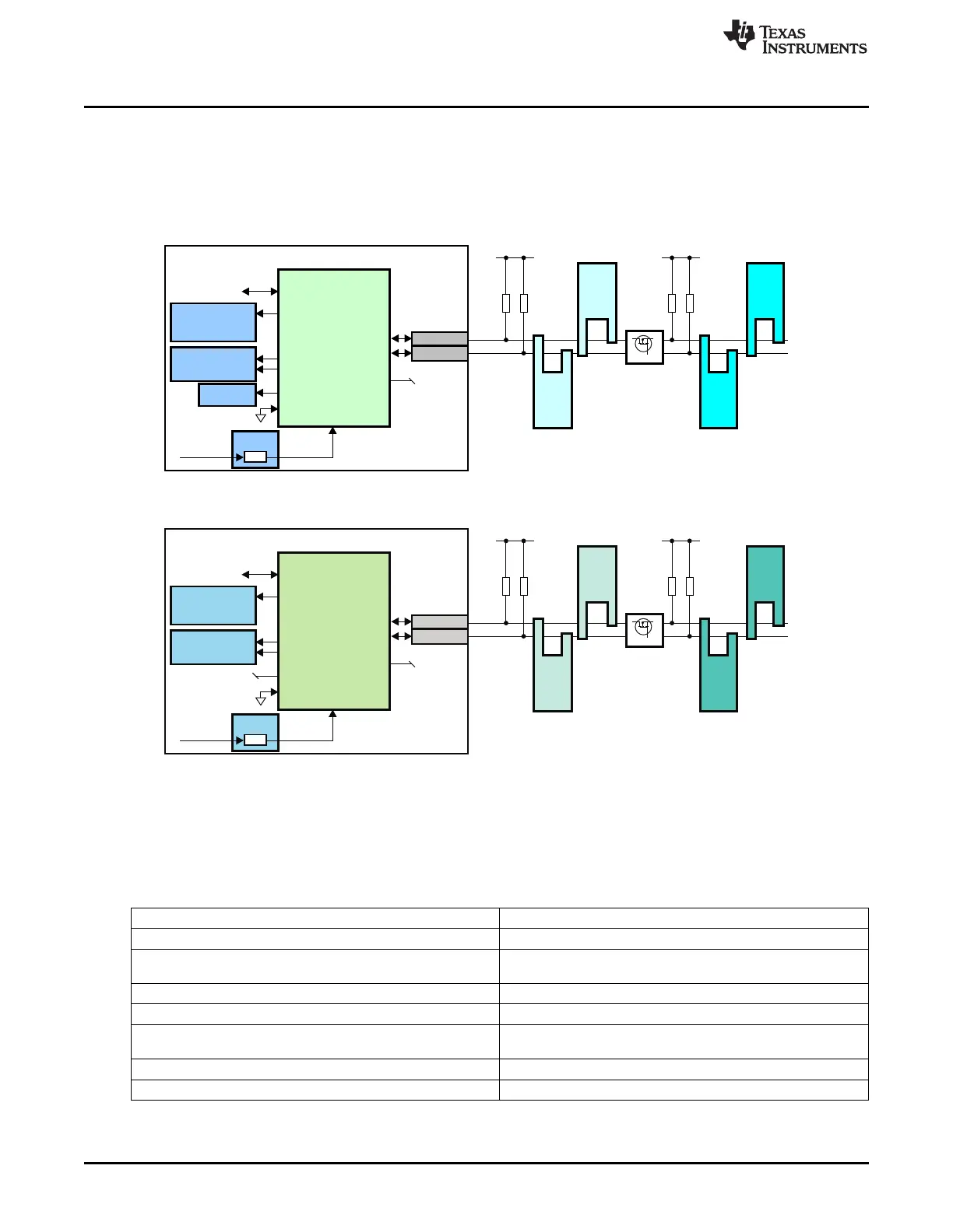
21.2 Integration
This device includes three instantiations of the I2C module. This peripheral implements the multi-master
I2C bus which allows serial transfer of 8-bit data to/from other I2C master/slave devices through a two-
wire interface. There are three I2C modules instantiations called I2C0, I2C1, and I2C2. The I2C0 module
is located in the Wake-up power domain. Figure 21-1 and Figure 21-2 show examples of a system with
multiple I2C-compatible devices.
Figure 21-1. I2C0 Integration and Bus Application
Figure 21-2. I2C(1–2) Integration and Bus Application
21.2.1 I2C Connectivity Attributes
The general connectivity attributes for the I2C module are shown in Table 21-2 and Table 21-3.
Table 21-2. I2C0 Connectivity Attributes
Attributes Type
Power Domain Wakeup Domain
Clock Domain PD_WKUP_L4_WKUP_GCLK (Interface/OCP)
PD_WKUP_I2C0_GFCLK (Func)
Reset Signals WKUP_DOM_RST_N
Idle/Wakeup Signals Smart Idle / Wakeup
Interrupt Requests 1 interrupt to MPU Subsystem (I2C0INT), PRU-ICSS, and
WakeM3
DMA Requests 2 DMA requests to EDMA (I2CTXEVT0, I2CRXEVT0)
Physical Address L4 Wakeup slave port
3700
I2C SPRUH73H–October 2011–Revised April 2013
Submit Documentation Feedback
Copyright © 2011–2013, Texas Instruments Incorporated

 Loading...


