TPCC
event_pi[63:0]
64
CFG Slave
From Event
Sources
(up to 128)
L3 Fast
Interconnect
TR Interface
Master
To TPTCs
Completion
Ports
Fr. TPTC0
Fr. TPTC1
Fr. TPTC2
mpint_pend_po
errint_pend_po
int_pend_po0
Host ARM
Interrupts
int_pend_po1
PRU-ICSS Interrupts
int_pend_po[3:2]
intg_pend_po
aet_po
Event
Crossbar
www.ti.com
Integration
11.2 Integration
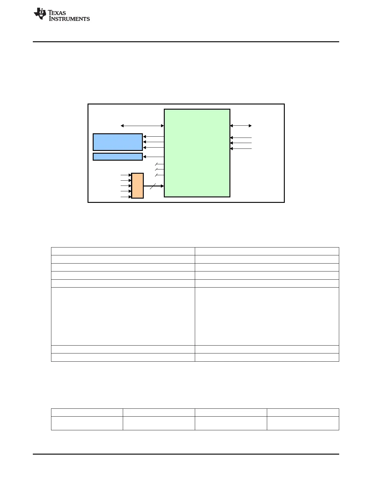
11.2.1 Third-Party Channel Controller (TPCC) Integration
This device uses the TPCC peripheral to provide control over its third-party transfer channels (TPTCs).
Figure 11-2 shows the integration of the TPCC module.
Figure 11-2. TPCC Integration
11.2.1.1 TPCC Connectivity Attributes
The general connectivity attributes of the TPCC are summarized in Table 11-1.
Table 11-1. TPCC Connectivity Attributes
Attributes Type
Power domain Peripheral Domain
Clock domain PD_PER_L3_GCLK
Reset signals PER_DOM_RST_N
Idle/Wakeup signals Smart Idle
Interrupt request
4 Regional Completion Interrupts:
int_pend_po0 (EDMACOMPINT) – to MPU Subsystem
int_pend_po1 (tpcc_int_pend_po1) – to PRU-ICSS
Int_pend_po[3:2] - unused
Error Interrupt:
errint_po (EDMAERRINT) – to MPU Subsystem
Memory Protection Error Interrupt:
mpint_p0 (EDMAMPERR) – to MPU Subsystem
DMA request none
Physical address L3 Fast slave port
11.2.1.2 TPCC Clock and Reset Management
The TPCC operates from a single clock and runs at the L3_Fast clock rate.
Table 11-2. TPCC Clock Signals
Clock Signal Max Freq Reference / Source Comments
tpcc_clk_pi 200 MHz CORE_CLKOUTM4 pd_per_l3_gclk
Interface / Functional clock From PRCM
873
SPRUH73H–October 2011–Revised April 2013 Enhanced Direct Memory Access (EDMA)
Submit Documentation Feedback
Copyright © 2011–2013, Texas Instruments Incorporated

 Loading...


