www.ti.com
Interrupt Controller Registers
6.5.1.44 INTC_ILR Register (offset = 100h to 2FCh) [reset = 0h]
INTC_ILR0 to INTC_ILR127 is shown in Figure 6-47 and described in Table 6-47.
The INTC_ILRx registers contain the priority for the interrupts and the FIQ/IRQ steering.
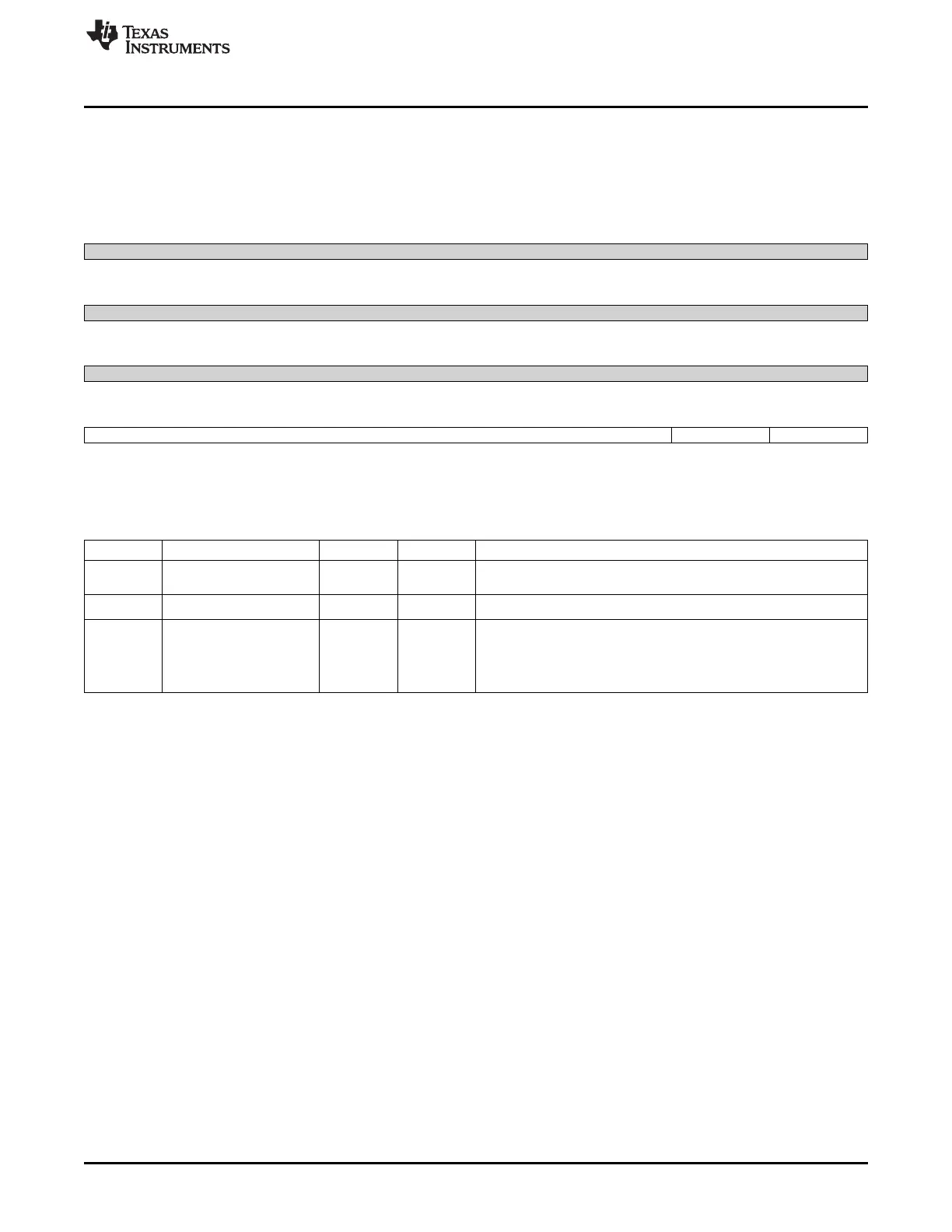
Figure 6-47. INTC_ILR0 to INTC_ILR127 Register
31 30 29 28 27 26 25 24
Reserved
R-0h
23 22 21 20 19 18 17 16
Reserved
R-0h
15 14 13 12 11 10 9 8
Reserved
R-0h
7 6 5 4 3 2 1 0
Priority Reserved FIQnIRQ
R/W-0h R/W-0h
LEGEND: R/W = Read/Write; R = Read only; W1toCl = Write 1 to clear bit; -n = value after reset
Table 6-47. INTC_ILR0 to INTC_ILR127 Register Field Descriptions
Bit Field Type Reset Description
31-8 Reserved R 0h Write 0's for future compatibility.
Reads returns 0
7-2 Priority R/W 0h
Interrupt priority
0 FIQnIRQ R/W 0h
Interrupt IRQ FiQ mapping
0x0 = IntIRQ : Interrupt is routed to IRQ.
0x1 = IntFIQ : Interrupt is routed to FIQ (this selection is reserved on
GP devices).
249
SPRUH73H–October 2011–Revised April 2013 Interrupts
Submit Documentation Feedback
Copyright © 2011–2013, Texas Instruments Incorporated

 Loading...


