Touchscreen Controller Registers
www.ti.com
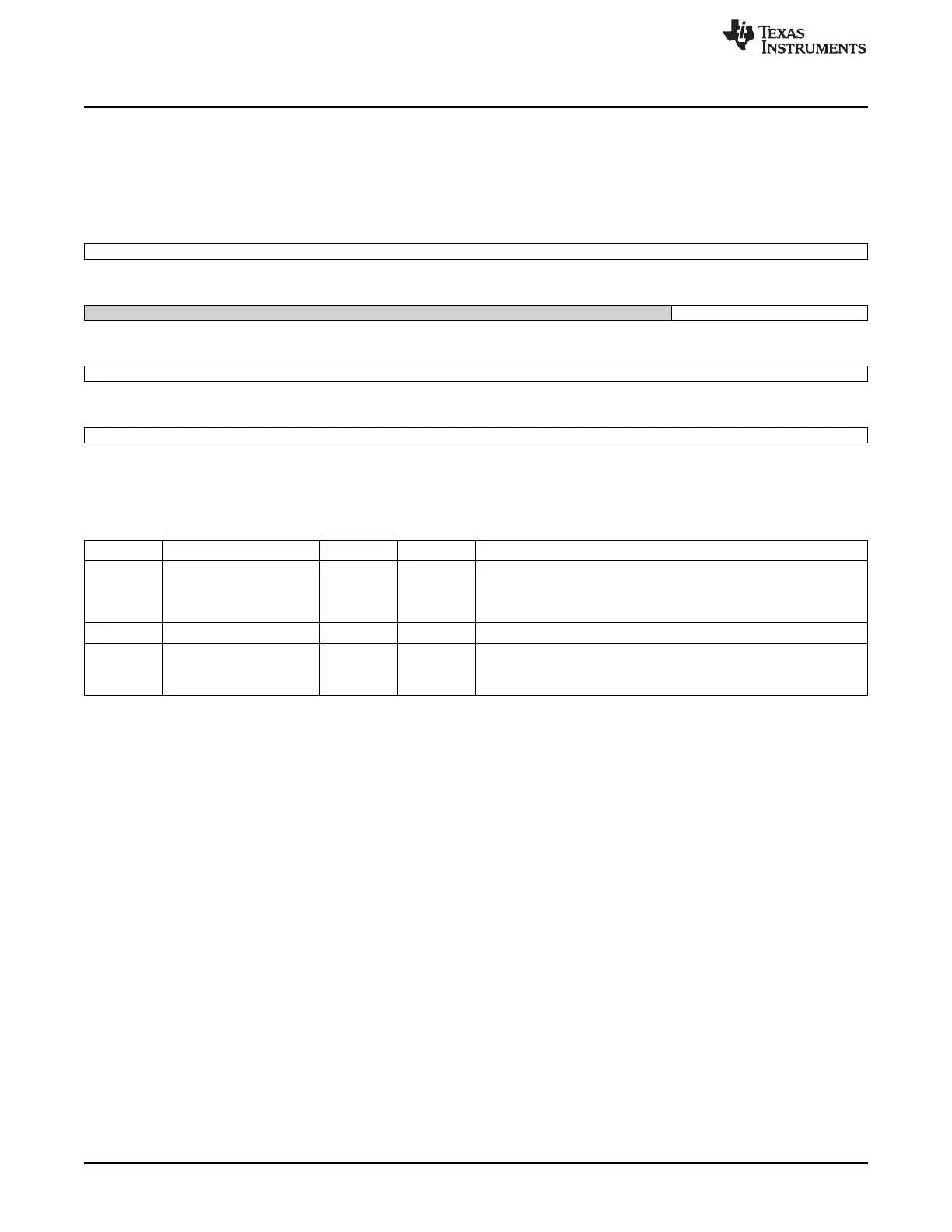
12.5.1.32 STEPDELAY7 Register (offset = 98h) [reset = 0h]
STEPDELAY7 is shown in Figure 12-36 and described in Table 12-36.
Step Delay Register 7
Figure 12-36. STEPDELAY7 Register
31 30 29 28 27 26 25 24
SampleDelay
R/W-0h
23 22 21 20 19 18 17 16
Reserved OpenDelay
R/W-0h R/W-0h
15 14 13 12 11 10 9 8
OpenDelay
R/W-0h
7 6 5 4 3 2 1 0
OpenDelay
R/W-0h
LEGEND: R/W = Read/Write; R = Read only; W1toCl = Write 1 to clear bit; -n = value after reset
Table 12-36. STEPDELAY7 Register Field Descriptions
Bit Field Type Reset Description
31-24 SampleDelay R/W 0h This register will control the number of ADC clock cycles to sample
(hold SOC high).
Any value programmed here will be added to the minimum
requirement of 1 clock cycle.
23-18 Reserved R/W 0h
17-0 OpenDelay R/W 0h
Program the number of ADC clock cycles to wait after applying the
step configuration registers and before sending the start of ADC
conversion
1070
Touchscreen Controller SPRUH73H–October 2011–Revised April 2013
Submit Documentation Feedback
Copyright © 2011–2013, Texas Instruments Incorporated

 Loading...


