www.ti.com
Power, Reset, and Clock Management
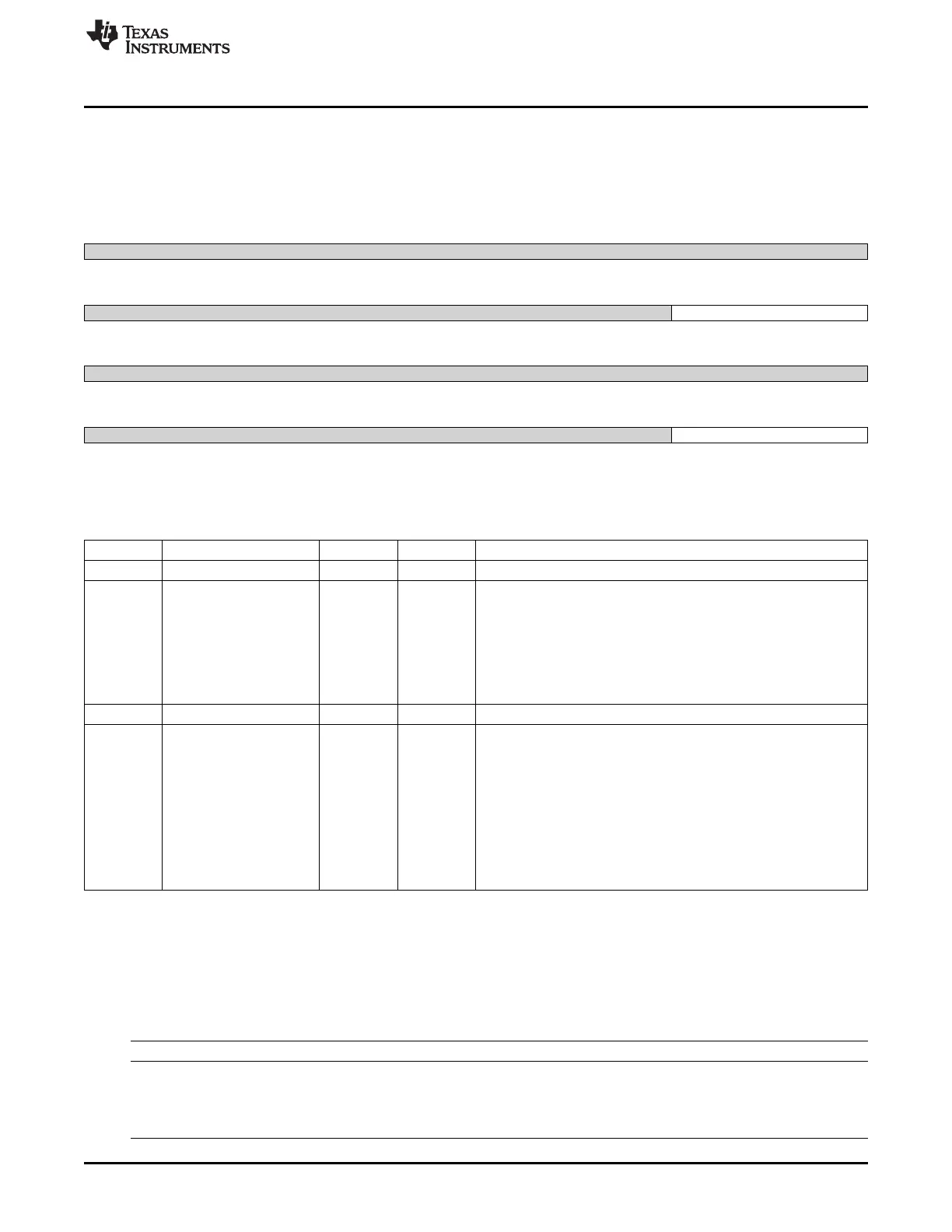
8.1.12.7.5 CM_GFX_MMUDATA_CLKCTRL Register (offset = 14h) [reset = 30000h]
CM_GFX_MMUDATA_CLKCTRL is shown in Figure 8-161 and described in Table 8-174.
This register manages the MMU clocks.
Figure 8-161. CM_GFX_MMUDATA_CLKCTRL Register
31 30 29 28 27 26 25 24
Reserved
R-0h
23 22 21 20 19 18 17 16
Reserved IDLEST
R-0h R-3h
15 14 13 12 11 10 9 8
Reserved
R-0h
7 6 5 4 3 2 1 0
Reserved MODULEMODE
R-0h R/W-0h
LEGEND: R/W = Read/Write; R = Read only; W1toCl = Write 1 to clear bit; -n = value after reset
Table 8-174. CM_GFX_MMUDATA_CLKCTRL Register Field Descriptions
Bit Field Type Reset Description
31-18 Reserved R 0h
17-16 IDLEST R 3h
Module idle status.
0x0 = Func : Module is fully functional, including OCP
0x1 = Trans : Module is performing transition: wakeup, or sleep, or
sleep abortion
0x2 = Idle : Module is in Idle mode (only OCP part). It is functional if
using separate functional clock
0x3 = Disable : Module is disabled and cannot be accessed
15-2 Reserved R 0h
1-0 MODULEMODE R/W 0h
Control the way mandatory clocks are managed.
0x0 = DISABLED : Module is disable by SW. Any OCP access to
module results in an error, except if resulting from a module wakeup
(asynchronous wakeup).
0x1 = RESERVED_1 : Reserved
0x2 = ENABLE : Module is explicitly enabled. Interface clock (if not
used for functions) may be gated according to the clock domain
state. Functional clocks are guarantied to stay present. As long as in
this configuration, power domain sleep transition cannot happen.
0x3 = RESERVED : Reserved
8.1.12.8 CM_CEFUSE Registers
Table 8-175 lists the memory-mapped registers for the CM_CEFUSE. All register offset addresses not
listed in Table 8-175 should be considered as reserved locations and the register contents should not be
modified.
Table 8-175. CM_CEFUSE REGISTERS
Offset Acronym Register Name Section
0h CM_CEFUSE_CLKSTCTRL This register enables the domain power state transition. Section 8.1.12.8.1
It controls the HW supervised domain power state
transition between ON-ACTIVE and ON-INACTIVE
states.
It also hold one status bit per clock input of the domain.
701
SPRUH73H–October 2011–Revised April 2013 Power, Reset, and Clock Management (PRCM)
Submit Documentation Feedback
Copyright © 2011–2013, Texas Instruments Incorporated

 Loading...


