www.ti.com
Ethernet Subsystem Registers
14.5.6.18 P1_MAX_BLKS Register (offset = 108h) [reset = 113h]
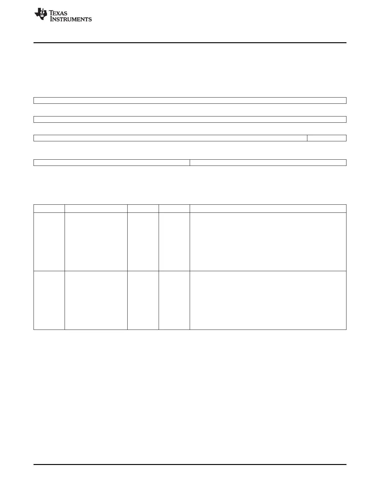
P1_MAX_BLKS is shown in Figure 14-138 and described in Table 14-153.
CPSW PORT 1 MAXIMUM FIFO BLOCKS REGISTER
Figure 14-138. P1_MAX_BLKS Register
31 30 29 28 27 26 25 24
Reserved
23 22 21 20 19 18 17 16
Reserved
15 14 13 12 11 10 9 8
Reserved P1_TX_MAX_BLKS
R/W-11h
7 6 5 4 3 2 1 0
P1_TX_MAX_BLKS P1_RX_MAX_BLKS
R/W-11h R/W-3h
LEGEND: R/W = Read/Write; R = Read only; W1toCl = Write 1 to clear bit; -n = value after reset
Table 14-153. P1_MAX_BLKS Register Field Descriptions
Bit Field Type Reset Description
8-4 P1_TX_MAX_BLKS R/W 11h Transmit FIFO Maximum Blocks - This value is the maximum
number of 1k memory blocks that may be allocated to the FIFO's
logical transmit priority queues.
0x11 is the recommended value of p1_tx_max_blks unless the port
is in fullduplex flow control mode.
In flow control mode, the p1_rx_max_blks will need to increase in
order to accept the required run out in fullduplex mode.
This value will need to decrease by the amount of increase in
p1_rx_max_blks.
0xe is the minimum value tx max blks.
3-0 P1_RX_MAX_BLKS R/W 3h Receive FIFO Maximum Blocks - This value is the maximum number
of 1k memory blocks that may be allocated to the FIFO's logical
receive queue.
This value must be greater than or equal to 0x3.
It should be increased In fullduplex flow control mode to 0x5 or 0x6
depending on the required runout space.
The p1_tx_max_blks value must be decreased by the amount of
increase in p1_rx_max_blks.
0x3 is the minimum value rx max blks and 0x6 is the maximum
value.
1375
SPRUH73H–October 2011–Revised April 2013 Ethernet Subsystem
Submit Documentation Feedback
Copyright © 2011–2013, Texas Instruments Incorporated

 Loading...


