Integration
www.ti.com
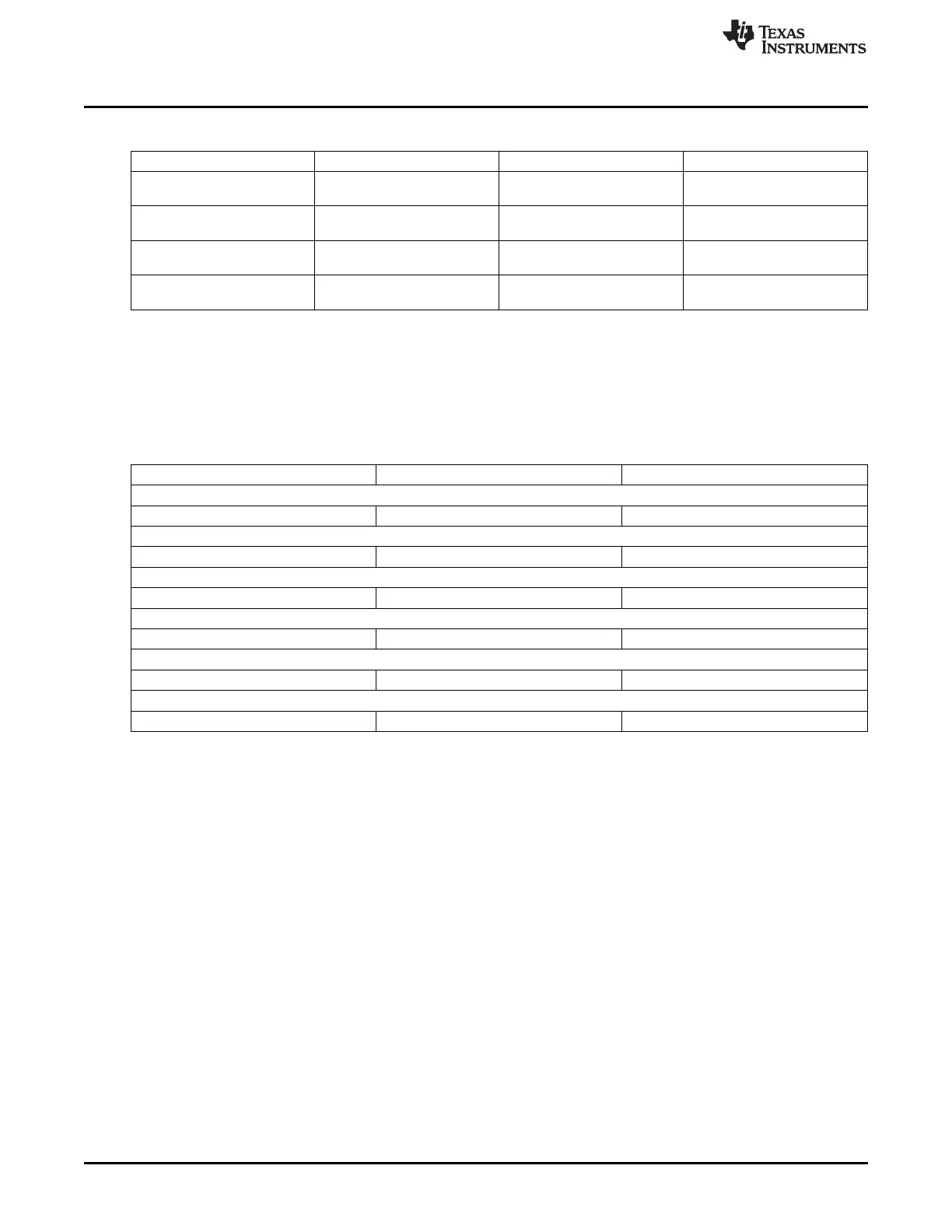
Table 25-3. GPIO Clock Signals (continued)
Clock Signal Max Freq Reference / Source Comments
Functional / Interface clock 100 MHz CORE_CLKOUTM4 / 2 pd_per_l4ls_gclk
From PRCM
Debounce Functional clock 32.768 KHz CLK_32KHZ pd_per_gpio_1_gdbclk
(GPIO1) (PER_CLKOUTM2 / 5859.375) From PRCM
Debounce Functional clock 32.768 KHz CLK_32KHZ pd_per_gpio_2_gdbclk
(GPIO2) (PER_CLKOUTM2 / 5859.375) From PRCM
Debounce Functional clock 32.768 KHz CLK_32KHZ pd_per_gpio_3_gdbclk
(GPIO3) (PER_CLKOUTM2 / 5859.375) From PRCM
25.2.3 GPIO Pin List
Each GPIO module includes 32 interface I/Os. These signals are designated as shown in Table 25-4.
Note that for this device, most of these signals will be multiplexed with functional signals from other
interfaces.
Table 25-4. GPIO Pin List
Pin Type Description
GPIO0
GPIO0_[31:0] I/O General Purpose Input-Output pins
GPIO1
GPIO1_[31:0] I/O General Purpose Input-Output pins
GPIO2
GPIO2_[31:0] I/O General Purpose Input-Output pins
GPIO3
GPIO3_[31:0] I/O General Purpose Input-Output pins
GPIO4
GPIO4_[31:0] I/O General Purpose Input-Output pins
GPIO5
GPIO5_[31:0] I/O General Purpose Input-Output pins
4060
General-Purpose Input/Output SPRUH73H–October 2011–Revised April 2013
Submit Documentation Feedback
Copyright © 2011–2013, Texas Instruments Incorporated
 Loading...


