www.ti.com
UART Registers
19.5.1.31 System Configuration Register (SYSC)
The AUTOIDLE bit controls a power-saving technique to reduce the logic power consumption of the
module interface; that is, when the feature is enabled, the interface clock is gated off until the module
interface is accessed. When the SOFTRESET bit is set high, it causes a full device reset. The system
configuration register (SYSC) is shown in Figure 19-64 and described in Table 19-62.
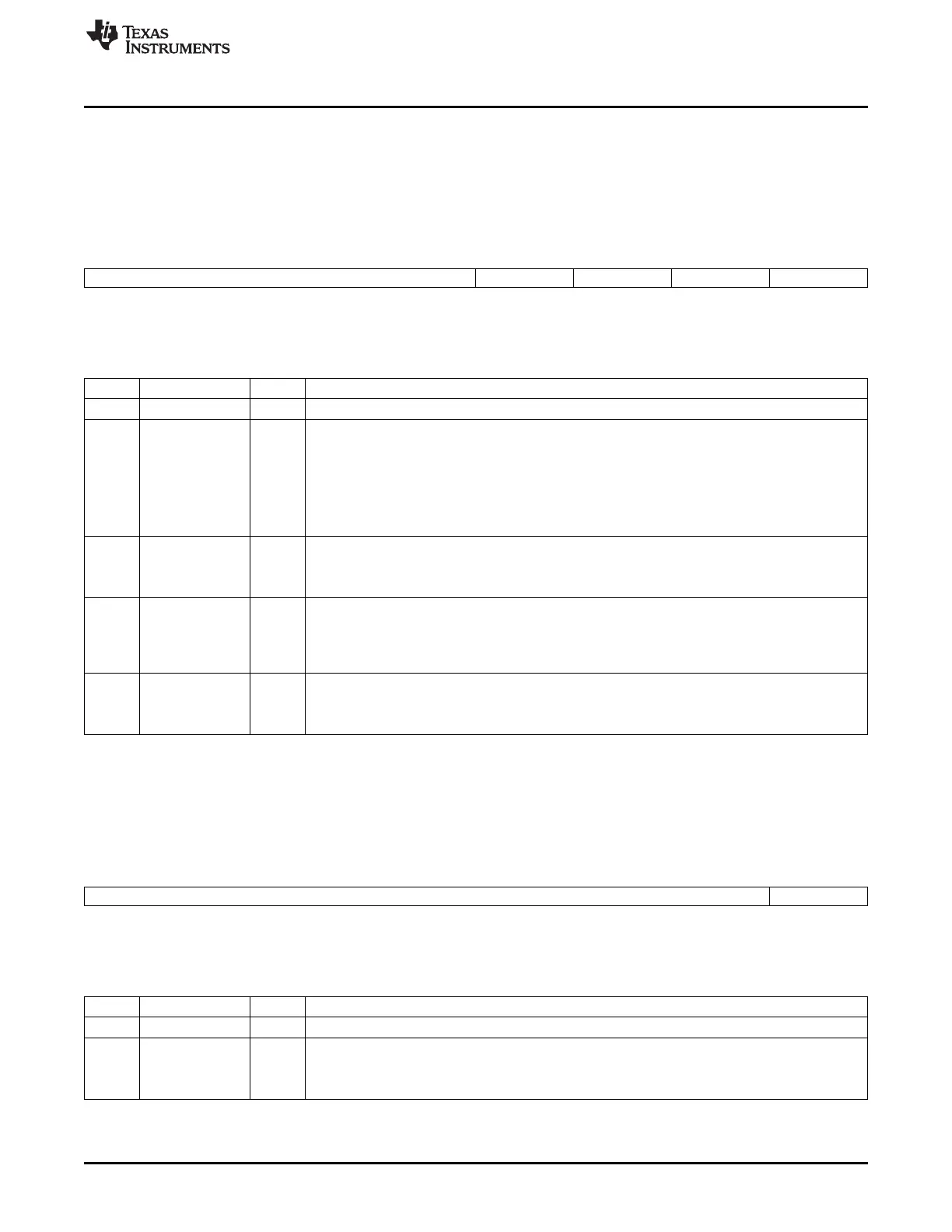
Figure 19-64. System Configuration Register (SYSC)
15 5 4 3 2 1 0
Reserved IDLEMODE ENAWAKEUP SOFTRESET AUTOIDLE
R-0 R/W-0 R/W-0 R/W-0 R/W-0
LEGEND: R/W = Read/Write; R = Read only; -n = value after reset
Table 19-62. System Configuration Register (SYSC) Field Descriptions
Bit Field Value Description
15-5 Reserved 0 Reserved.
4-3 IDLEMODE 0-3h Power management req/ack control.
0 Force idle: Idle request is acknowledged unconditionally.
1h No-idle: Idle request is never acknowledged.
2h Smart idle: Acknowledgement to an idle request is given based in the internal activity of the module.
3h Smart idle Wakeup: Acknowledgement to an idle request is given based in the internal activity of
the module. The module is allowed to generate wakeup request. Only available on UART0.
2 ENAWAKEUP Wakeup control.
0 Wakeup is disabled.
1 Wakeup capability is enabled.
1 SOFTRESET Software reset. Set this bit to 1 to trigger a module reset. This bit is automatically reset by the
hardware. Read returns 0.
0 Normal mode.
1 Module is reset.
0 AUTOIDLE Internal interface clock-gating strategy.
0 Clock is running.
1 Reserved.
19.5.1.32 System Status Register (SYSS)
The system status register (SYSS) is shown in Figure 19-65 and described in Table 19-63.
Figure 19-65. System Status Register (SYSS)
15 1 0
Reserved RESETDONE
R-0 R-0
LEGEND: R/W = Read/Write; R = Read only; -n = value after reset
Table 19-63. System Status Register (SYSS) Field Descriptions
Bit Field Value Description
15-1 Reserved 0 Reserved.
0 RESETDONE Internal reset monitoring.
0 Internal module reset is ongoing.
1 Reset complete.
3533
SPRUH73H–October 2011–Revised April 2013 Universal Asynchronous Receiver/Transmitter (UART)
Submit Documentation Feedback
Copyright © 2011–2013, Texas Instruments Incorporated

 Loading...


