www.ti.com
LCD Registers
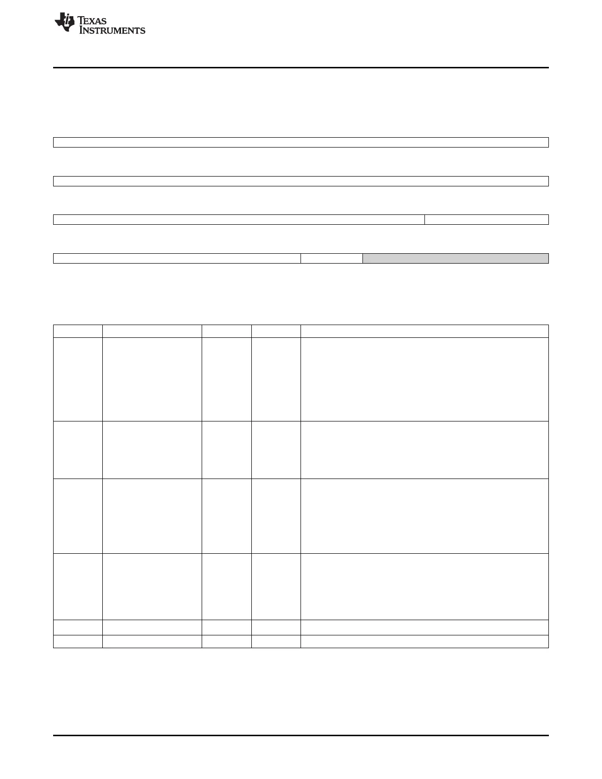
13.5.11 RASTER_TIMING_0 Register (offset = 2Ch) [reset = 0h]
RASTER_TIMING_0 is shown in Figure 13-29 and described in Table 13-24.
Figure 13-29. RASTER_TIMING_0 Register
31 30 29 28 27 26 25 24
hbp
R/W-0h
23 22 21 20 19 18 17 16
hfp
R/W-0h
15 14 13 12 11 10 9 8
hsw ppllsb
R/W-0h R/W-0h
7 6 5 4 3 2 1 0
ppllsb pplmsb Reserved
R/W-0h R/W-0h R-0h
LEGEND: R/W = Read/Write; R = Read only; W1toCl = Write 1 to clear bit; -n = value after reset
Table 13-24. RASTER_TIMING_0 Register Field Descriptions
Bit Field Type Reset Description
31-24 hbp R/W 0h Horizontal Back Porch Lowbits Bits 7:0 of the horizontal back porch
field
Encoded value (from 1-1024) used to specify the number of pixel
clock periods to add to the beginning of a line transmission before
the first set of pixels is output to the display (programmed value plus
1)
Note that pixel clock is held in its inactive state during the beginning
of the line wait period in passive display mode, and is permitted to
transition in active display mode
23-16 hfp R/W 0h Horizontal Front Porch Lowbits Encoded value (from 1-1024) used to
specify the number of pixel clock periods to add to the end of a line
transmission before line clock is asserted (programmed value plus 1)
Note that pixel clock is held in its inactive state during the end of line
wait period in passive display mode, and is permitted to transition in
active display mode
15-10 hsw R/W 0h Horizontal Sync Pulse Width Lowbits Bits 5:0 of the horizontal sync
pulse width field
Encoded value (from 1-1024) used to specify the number of pixel
clock periods to pulse the line clock at the end of each line
(programmed value plus 1)
Note that pixel clock is held in its inactive state during the generation
of line clock in passive display mode, and is permitted to transition in
active display mode
9-4 ppllsb R/W 0h Pixels-per-line LSB[9:4] Encoded LSB value (from 1-1024) used to
specify the number of pixels contained within each line on the LCD
display (programmed to value minus one)
PPL = 11'b{pplmsb, ppllsb, 4'b1111} + 1 ex: pplmsb=1'b1,
pppllsb=6'0001000 PPL = 11'b{1, 000100, 1111}+ 1 = 1104d
(decimal) pixels per line
In other words, PPL = 16*({pplmsb, ppllsb}+1)
3 pplmsb R/W 0h
Pixels-per-line MSB[10] Needed in order to support up to 2048 ppl
2-0 Reserved R 0h
1141
SPRUH73H–October 2011–Revised April 2013 LCD Controller
Submit Documentation Feedback
Copyright © 2011–2013, Texas Instruments Incorporated

 Loading...


