LCD Registers
www.ti.com
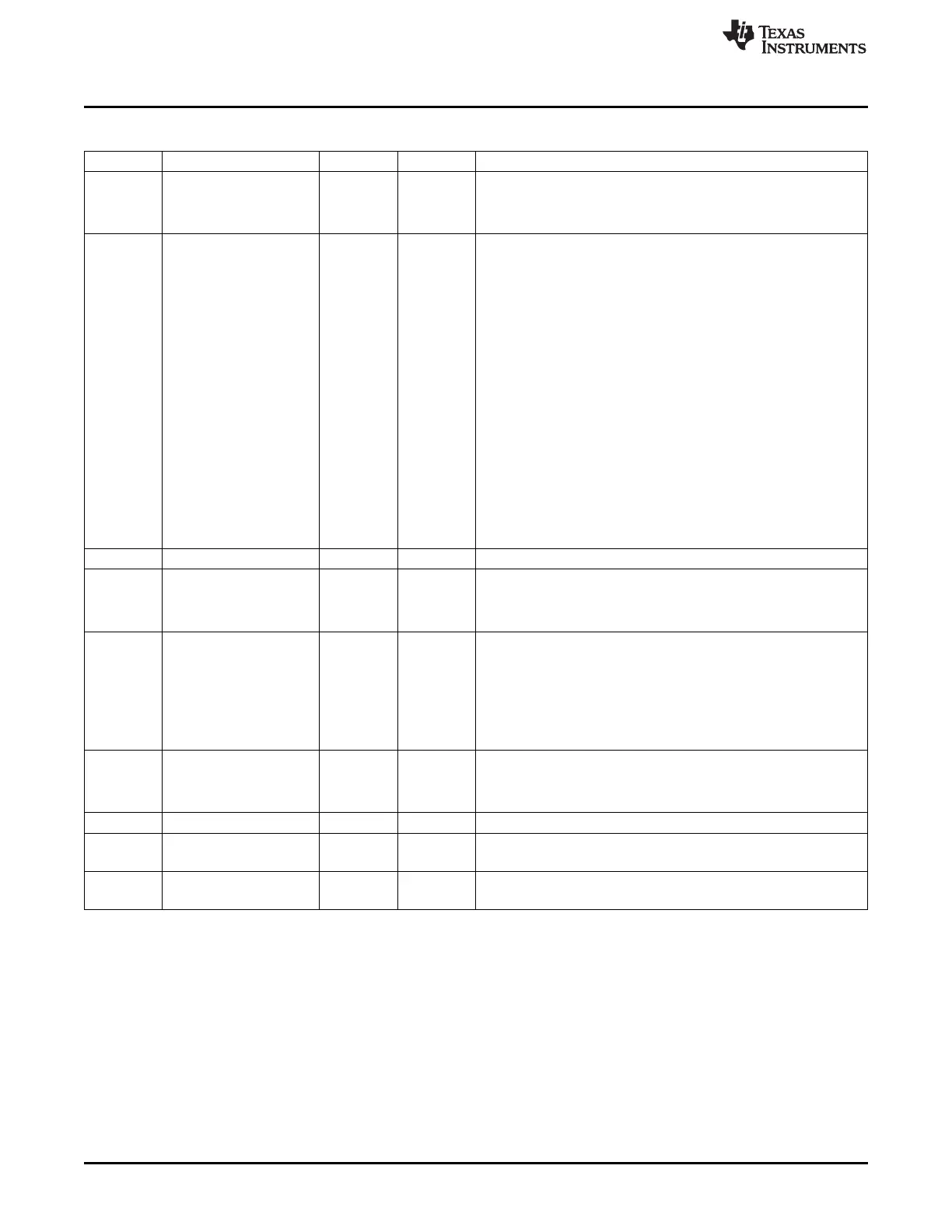
Table 13-23. RASTER_CTRL Register Field Descriptions (continued)
Bit Field Type Reset Description
21-20 palmode R/W 0h Palette Loading Mode 00: Palette and data loading, reset value 01:
Palette loading only 10: Data loading only For Raw Data (12/16/24
bpp) framebuffers, no palette lookup is employed
Thus, these framebuffers should use the data-only loading mode
19-12 reqdly R/W 0h Palette Loading Delay When loading the Palette from DDR, palette
data is burst into the internal Palette SRAM from the Async FIFO
1-, 2-, and 4-bit per pixel framebuffer encodings use a fixed 16-word
entry palette residing above the video data
The 8 bit per pixel framebuffer encoding uses a 256-word entry
palette residing above the video data
Likewise, 12, 16, and 24 bit per pixel framebuffer encodings also
define a 256-word entry palette even though these encodings will not
do a full bit-depth palette lookup
However, the 256-word palette entry must still be read from DDR as
a framebuffer is fetched
Bursting in 256 words in sequential lcd_clk cycles may cause the
Async FIFO to underflow depending on the SOC DDR burst
bandwidth
This 8-bit reqdly parameter pauses reading of the Palette data from
the Async FIFO between each burst of 16 words
The delay is in terms of lcd_clk (system clock) cycles
Value (0-255) used to specify the number of system clock cycles that
should be paused between bursts of 16 word reads from the Async
FIFO while loading the Palette SRAM
Programming reqdly=00h disables this pause when loading the
palette table
11-10 Reserved R/W 0h
9 nono8b R/W 0h Mono 8 bit 0: lcd_pixel_o\[3:0\] is used to output four pixel values to
the panel each pixel clock transition 1: lcd_pixel_o\[7:0\] is used to
output eight pixel values to the panel each pixel clock transition
This bit is ignored in all other modes
8 rdorder R/W 0h Raster Data Order Select 0: The frame buffer parsing for Palette
Data lookup is from Bit 0 to bit 31 of the input word from the DMA
output
1: The fame buffer parsing for Palette Data lookup is from Bit 31 to
Bit 0 of the input word from the DMA output
This bit has no effect on raw data framebuffers (12/16/24 bpp)
This bit is used to determine palette indexing and is used in
conjunction with cfg_nibmode
7 lcdtft R/W 0h LCD 0: Passive or display operation enabled, dither logic is enabled
1: Active or display operation enabled, external palette and DAC
required, dither logic bypassed, pin timing changes to support
continuous pixel clock, output enable, vsync, and hsync
6-2 Reserved R/W 0h
1 lcdbw R/W 0h
Only Applies for Passive Matrix Panels LCD Monochrome 0: Color
operation enabled 1: Monochrome operation enabled
0 lcden R/W 0h
LCD Controller Enable 0: LCD controller disabled 1: LCD controller
enabled
1140
LCD Controller SPRUH73H–October 2011–Revised April 2013
Submit Documentation Feedback
Copyright © 2011–2013, Texas Instruments Incorporated

 Loading...


