GPMC
www.ti.com
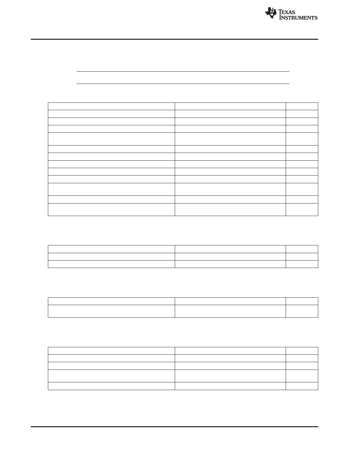
7.1.3.6 GPMC Configuration in NOR Mode
This section gives a generic configuration for parameters related to the NOR memory connected to the
GPMC. Table 7-27 through Table 7-31 list the steps to configure the GPMC in NOR mode.
NOTE: In the tables of this section, 'x' in Value column stands for 'depends on configuration'.
Table 7-27. NOR Memory Type
Sub-process Name Register / Bitfield Value
Set the NOR protocol GPMC_CONFIG1_i[11-10] DEVICETYPE 0
Set a device size GPMC_CONFIG1_i[13-12] DEVICESIZE x
Select an address and data multiplexing protocol GPMC_CONFIG1_i[9] MUXADDDATA x
GPMC_CONFIG1_i[24-23]
Set the attached device page length x
ATTACHEDDEVICEPAGELENGTH
Set the wrapping burst capabilities GPMC_CONFIG1_i[31] WRAPBURST x
Select a timing signals latencies factor GPMC_CONFIG1_i[4] TIMEPARAGRANULARITY x
Select an output clock frequency GPMC_CONFIG1_i[1-0] GPMCFCLKDIVIDER x
Choose an output clock activation time GPMC_CONFIG1_i[26-25] CLKACTIVATIONTIME x
Set a single or multiple access for read operations GPMC_CONFIG1_i[30] READMULTIPLE x
Set a synchronous or asynchronous mode for read
GPMC_CONFIG1_i[29] READTYPE x
operations
Set a single or multiple access for write operations GPMC_CONFIG1_i[28] WRITEMULTIPLE x
Set a synchronous or asynchronous mode for write
GPMC_CONFIG1_i[27] WRITETYPE x
operations
Table 7-28. NOR Chip-Select Configuration
Sub-process Name Register / Bitfield Value
Select the chip-select base address GPMC_CONFIG7_i[5-0] BASEADDRESS x
Select the chip-select mask address GPMC_CONFIG7_i[11-8] MASKADDRESS x
Table 7-29. NOR Timings Configuration
Sub-process Name Register / Bitfield Value
Configure adequate timing parameters in various memory
See Section 7.1.3.9
modes
Table 7-30. WAIT Pin Configuration
Sub-process Name Register / Bitfield Value
Enable or disable wait pin monitoring for read operations GPMC_CONFIG1_i[22] WAITREADMONITORING x
Enable or disable wait pin monitoring for write operations GPMC_CONFIG1_i[21] WAITWRITEMONITORING x
GPMC_CONFIG1_i[19-18]
Select a wait pin monitoring time x
WAITMONITORINGTIME
Choose the input wait pin for the chip-select GPMC_CONFIG1_i[17-16] WAITPINSELECT x
338
Memory Subsystem SPRUH73H–October 2011–Revised April 2013
Submit Documentation Feedback
Copyright © 2011–2013, Texas Instruments Incorporated

 Loading...


