Gray-scaler/
serializer
Output
FIFO
Palette
RAM
Input
FIFO
MUX
STN
TFT
Raster
controller
MUX
Registers
LIDD
controller
LCD_D[23:0]
MUX
LCD block
LCD_VSYNC
LCD_HSYNC
LCD_PCLK
LCD_MCLK
LCD_AC_ENB_CS
DMA
control
registers
DMA
DMA
block
LCD_CLK
CPU
read/
write
Introduction
www.ti.com
13.1 Introduction
13.1.1 Purpose of the Peripheral
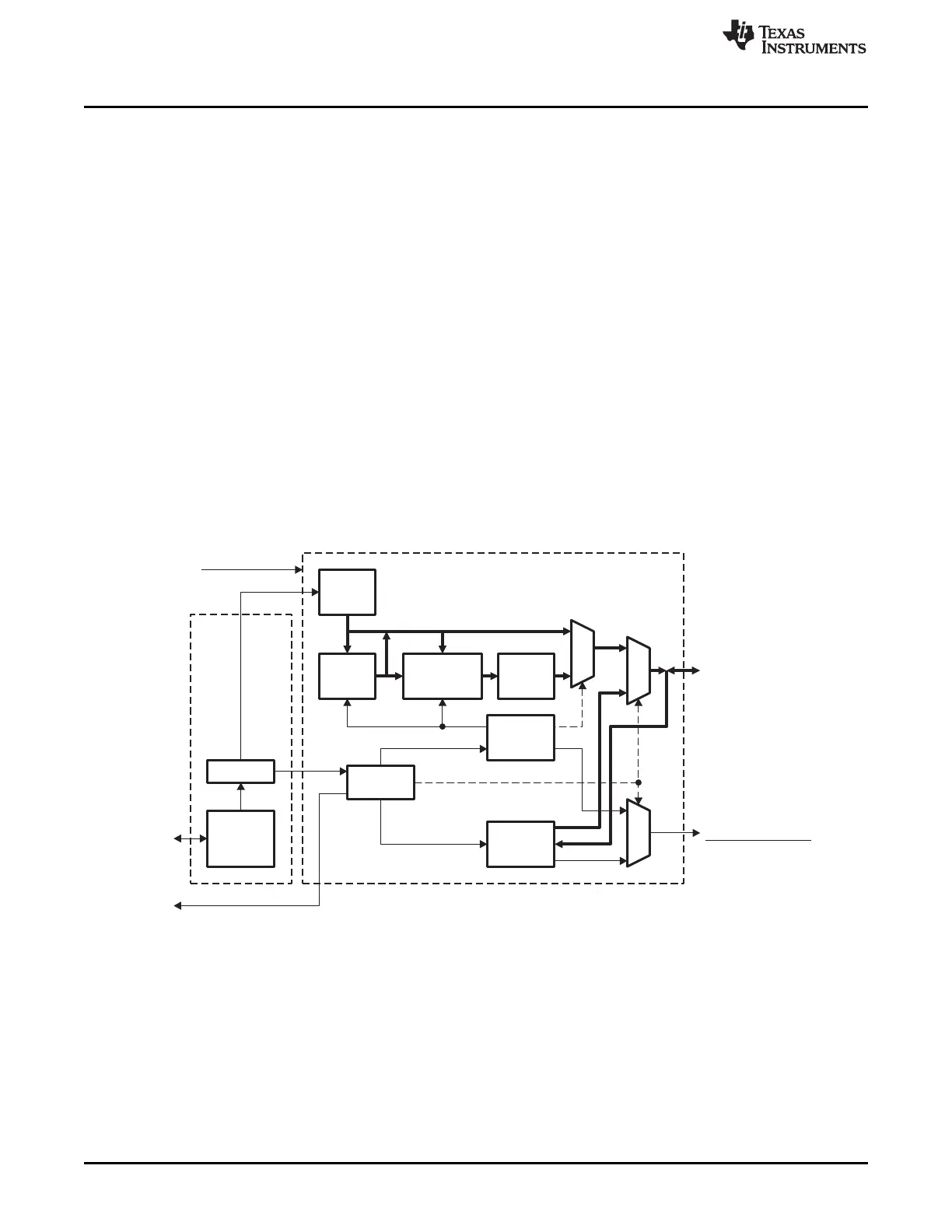
The LCD controller consists of two independent controllers, the Raster Controller and the LCD Interface
Display Driver (LIDD) controller. Each controller operates independently from the other and only one of
them is active at any given time.
• The Raster Controller handles the synchronous LCD interface. It provides timing and data for constant
graphics refresh to a passive display. It supports a wide variety of monochrome and full-color display
types and sizes by use of programmable timing controls, a built-in palette, and a gray-scale/serializer.
Graphics data is processed and stored in frame buffers. A frame buffer is a contiguous memory block
in the system. A built-in DMA engine supplies the graphics data to the Raster engine which, in turn,
outputs to the external LCD device.
• The LIDD Controller supports the asynchronous LCD interface. It provides full-timing programmability
of control signals (CS, WE, OE, ALE) and output data.
Figure 13-1 shows the LCD controller details. The raster and LIDD Controllers are responsible for
generating the correct external timing. The DMA engine provides a constant flow of data from the frame
buffer(s) to the external LCD panel via the Raster and LIDD Controllers. In addition, CPU access is
provided to read and write registers.
The solid, thick lines in Figure 13-1 indicate the data path. The Raster Controller's data path is fairly
complicated, for a thorough description of the Raster Controller data path, see Section 13.3.5.
Figure 13-1. LCD Controller
1098
LCD Controller SPRUH73H–October 2011–Revised April 2013
Submit Documentation Feedback
Copyright © 2011–2013, Texas Instruments Incorporated

 Loading...


