UART/IrDA/CIR
Controller
L4 Peripheral
Interconnect
MPU Subsystem,
PRU-ICSS,
Wakeup Ctrl
Interrupts
EDMA
IRQ
DMAREQ0
DMAREQ1
FCLK
PER_CLKOUTM2
(192 MHz)
PRCM
/4
Register/FIFO
Interface
IrDA/CIR
Transceiver
UART
Pads
UARTx_IRTX
UARTx_IRRX
UARTx_SD
UARTx_RCTX
RXD (IrDA)
SD/MODE
TXD
RC (CIR)
UART/IrDA/CIR
Controller
L4 Peripheral
Interconnect
UART/Modem
UART
Pads
MPU Subsystem,
PRU-ICSS,
Wakeup Ctrl
Interrupts
EDMA
IRQ
DMAREQ0
DMAREQ1
FCLK
UARTx_RXD
UARTx_TXD
UARTx_RTSn
UARTx_CTSn
UARTx_DTRn
UARTx_DSRn
RX
RTS
UARTx_DCDn
UARTx_RIN
TX
CTS
DTR
DSR
DCD
RIN
PER_CLKOUTM2
(192 MHz)
PRCM
/4
Register/FIFO
Interface
www.ti.com
Integration
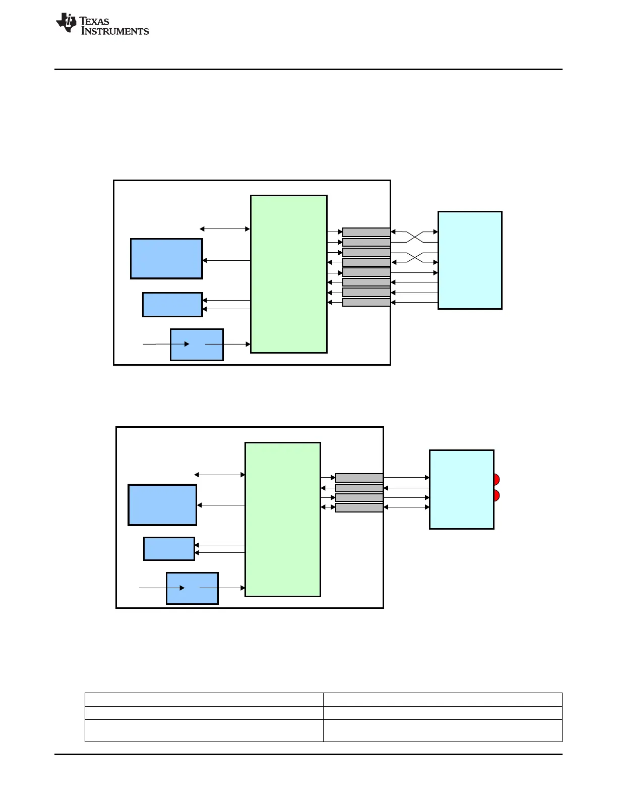
19.2 Integration
This device contains 6 instantiations of the UART/IrDA (UARTIRDAOCP) peripheral. There are six UART
modules called UART0 – UART5. UART0 provides wakeup capability. Only UART 1 provides full modem
control signals. All UARTs support IrDA and CIR modes and RTS/CTS flow control (subject to pin muxing
configuration). Figure 19-1 shows an example of system connectivity using UART communication with
hardware handshake.
Figure 19-1. UART/IrDA Module — UART Application
Figure 19-2 shows an example of system connectivity using infrared communication with remote control
(consumer infrared).
Figure 19-2. UART/IrDA Module — IrDA/CIR Application
19.2.1 UART Connectivity Attributes
The general connectivity attributes for each of the UART modules are shown in Table 19-2 and Table 19-
3.
Table 19-2. UART0 Connectivity Attributes
Attributes Type
Power Domain Wake-Up Domain
Clock Domain PD_WKUP_L4_WKUP_GCLK (OCP)
PD_WKUP_UART0_GFCLK (Func)
3449
SPRUH73H–October 2011–Revised April 2013 Universal Asynchronous Receiver/Transmitter (UART)
Submit Documentation Feedback
Copyright © 2011–2013, Texas Instruments Incorporated

 Loading...


