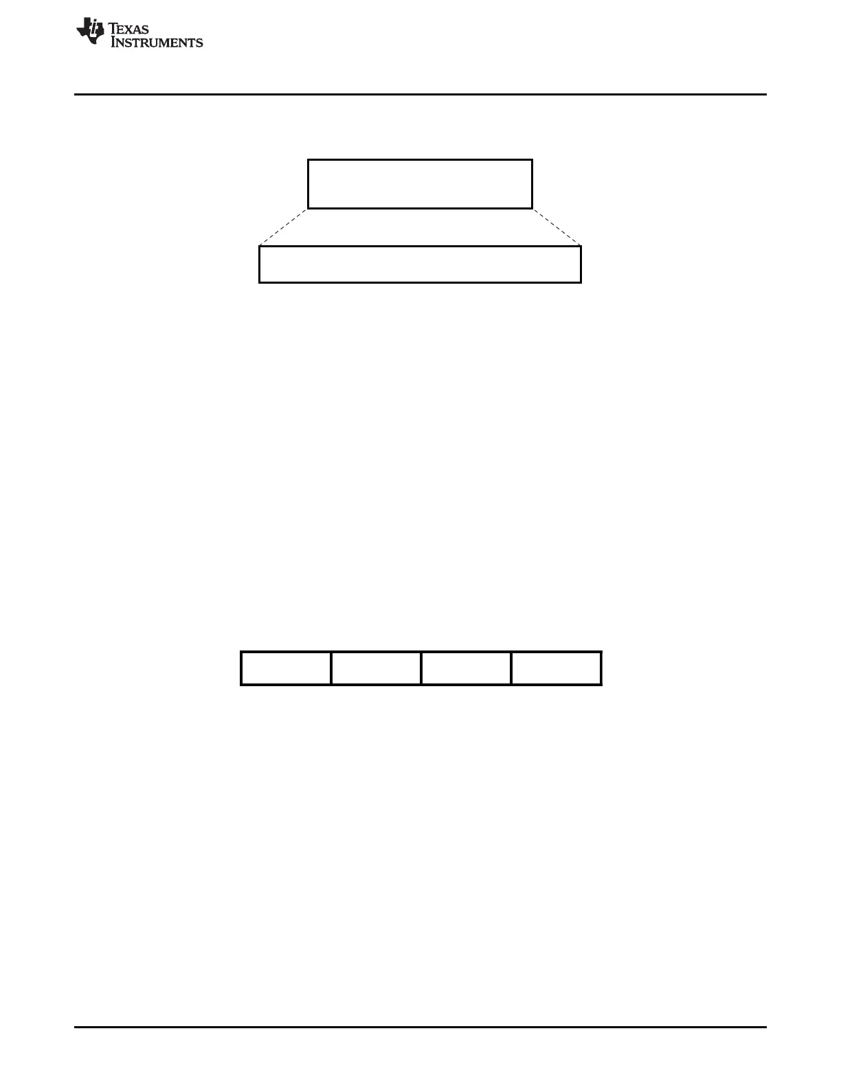
Start Flags
Frame Data
CRC - 16
Stop Flag
FIFO DATA
Fre e Form at
M * 8 bits
www.ti.com
Functional Description
Figure 19-19. SIR Free Format Mode
In this mode, the entire FIFO data packet is to be constructed (encoded and decoded) by the LH software.
The SIR free format mode is selected by setting the module in UART mode (MDR1[2:0] = 000) and the
MDR2[3] register bit to one to allow the pulse shaping. As the bit format is to remain the same, some
UART mode configuration registers need to be set at specific value:
• LCR[1:0] = “11” (8 data bits)
• LCR[2] = 0 (1 stop bit)
• LCR[3] = 0 (no parity)
• ACREG[7] = 0 (3/16 of baud-rate pulse width)
The features defined through MDR2[6] and ACREG[5] are also supported.
Note: - All other configuration registers need to be at the reset value. The UART mode interrupts are used
for the SIR free format mode, but many of them are not relevant (e.g., XOFF, RTS, CTS, Modem status
register).
19.3.8.2.2 MIR Mode
In medium infrared (MIR) mode, data transfers take place between LH and peripheral devices at 0.576 or
1.152 Mbits/s speed. A MIR transmit frame starts with start flags (at least two), followed by a frame data,
CRC-16, and ends with a stop flag.
Figure 19-20. MIR Transmit Frame Format
On transmit, the MIR state machine attaches start flags, CRC-16, and stop flags. It also looks for five
consecutive values of 1 in the frame data and automatically inserts a zero after five consecutive values of
one (this is called bit stuffing).
On receive, the MIR receive state machine recovers the receive clock, removes the start flags, de-stuffs
the incoming data, and determines frame boundary with reception of the stop flag. It also checks for
errors, such as frame abort, CRC error, or frame-length error. At the end of a frame reception, the LH
reads the line status register (LSR) to find possible errors of received frame.
Data can be transferred both ways by the module but when the device is transmitting, the IR RX circuitry
is automatically disabled by hardware. See bit 5 in Section 19.5.1.26, Auxiliary Control Register, for a
description of the logical operation. Note: This applies to all three modes SIR, MIR and FIR.
19.3.8.2.2.1 MIR Encoder/Decoder
In order to meet MIR baud-rate tolerance of +/-0.1% with a 48-MHz clock input, a 42-41-42
encoding/decoding adjustment is performed. The reference start point is the first start flag and the 42-41-
42 cyclic pattern is repeated until the stop flag is sent or detected. The jitter created this way is within MIR
tolerances. The pulse width is not exactly 1/4 but within tolerances defined by the IrDA specifications.
3483
SPRUH73H–October 2011–Revised April 2013 Universal Asynchronous Receiver/Transmitter (UART)
Submit Documentation Feedback
Copyright © 2011–2013, Texas Instruments Incorporated

 Loading...


