Power, Reset, and Clock Management
www.ti.com
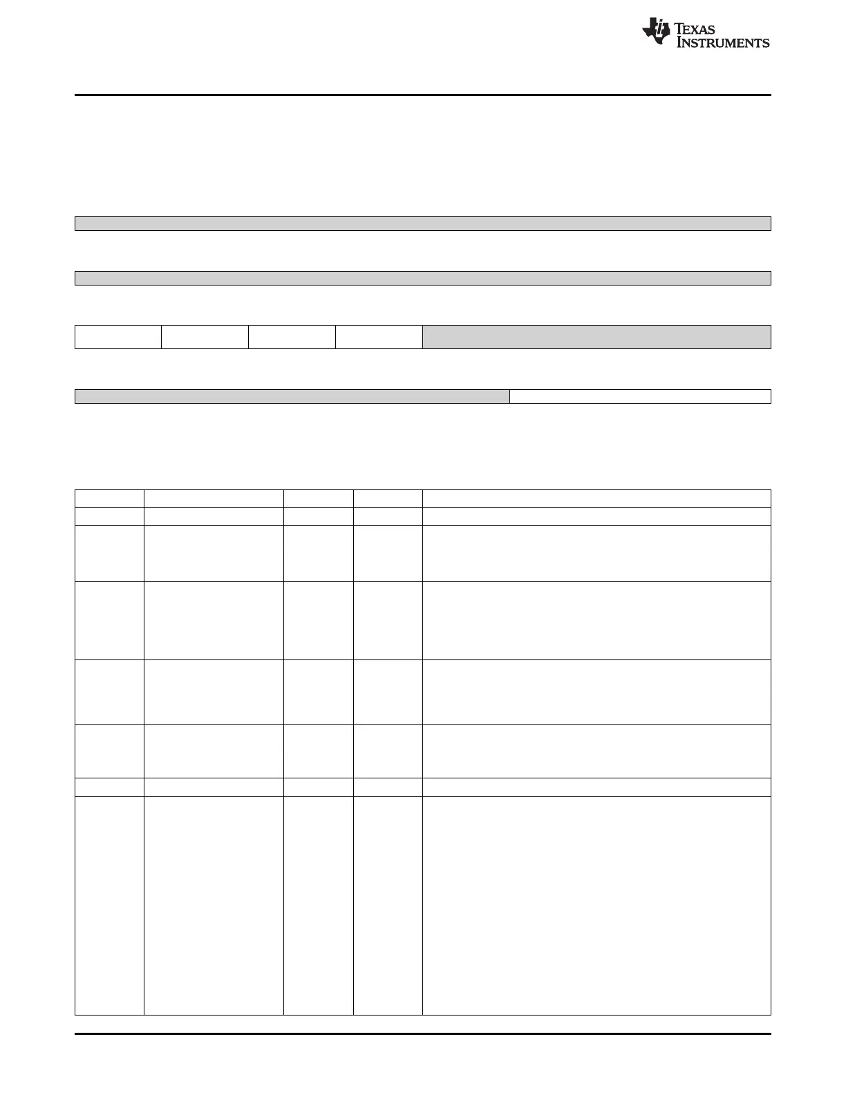
8.1.12.2.36 CM_CLKMODE_DPLL_PER Register (offset = 8Ch) [reset = 4h]
CM_CLKMODE_DPLL_PER is shown in Figure 8-119 and described in Table 8-127.
This register allows controlling the DPLL modes.
Figure 8-119. CM_CLKMODE_DPLL_PER Register
31 30 29 28 27 26 25 24
Reserved
R-0h
23 22 21 20 19 18 17 16
Reserved
R-0h
15 14 13 12 11 10 9 8
DPLL_SSC_TYPE DPLL_SSC_DOWNS DPLL_SSC_ACK DPLL_SSC_EN Reserved
PREAD
R/W-0h R/W-0h R-0h R/W-0h R-0h
7 6 5 4 3 2 1 0
Reserved DPLL_EN
R-0h R/W-4h
LEGEND: R/W = Read/Write; R = Read only; W1toCl = Write 1 to clear bit; -n = value after reset
Table 8-127. CM_CLKMODE_DPLL_PER Register Field Descriptions
Bit Field Type Reset Description
31-16 Reserved R 0h
15 DPLL_SSC_TYPE R/W 0h Select Triangular Spread Spectrum clocking.
Always write 0.
0 = Triangular Spread Spectrum Clocking is selected.
1 = Reserved.
14 DPLL_SSC_DOWNSPRE R/W 0h
Control if only low frequency spread is required
AD
0x0 = FULL_SPREAD : When SSC is enabled, clock frequency is
spread on both sides of the programmed frequency
0x1 = LOW_SPREAD : When SSC is enabled, clock frequency is
spread only on the lower side of the programmed frequency
13 DPLL_SSC_ACK R 0h
Acknowledgement from the DPLL regarding start and stop of Spread
Spectrum Clocking feature
0x0 = Disabled : SSC has been turned off on PLL o/ps
0x1 = Enabled : SSC has been turned on on PLL o/ps
12 DPLL_SSC_EN R/W 0h
Enable or disable Spread Spectrum Clocking
0x0 = Disabled : SSC disabled
0x1 = Enabled : SSC enabled
11-3 Reserved R 0h
2-0 DPLL_EN R/W 4h DPLL control.
Upon Warm Reset, the PRCM DPLL control state machine updates
this register to reflect DPLL Low Power Stop mode.
0x0 = Reserved : Reserved
0x1 = DPLL_LP_STP_MODE : Put the DPLL in Low Power Stop
mode
0x2 = Reserved2 : Reserved2
0x3 = Reserved3 : Reserved
0x4 = DPLL_MN_BYP_MODE : Put the DPLL in MN Bypass mode.
The DPLL_MULT register bits are reset to 0 automatically by putting
the DPLL in this mode.
0x5 = DPLL_LP_BYP_MODE : Put the DPLL in Idle Bypass Low
Power mode.
0x6 = Reserved6 : Reserved
0x7 = DPLL_LOCK_MODE : Enables the DPLL in Lock mode
652
Power, Reset, and Clock Management (PRCM) SPRUH73H–October 2011–Revised April 2013
Submit Documentation Feedback
Copyright © 2011–2013, Texas Instruments Incorporated

 Loading...


