TPIR
3 2
TNIR
TCVR
1
0
MS B
Co n v ers io n
TLDR
3 2
3 2
TOCR
24 Bit Counter
TOWR
2 4
2 4
2 4
OVF
Full
Filtered Overflow
(to TISR)
DM Timer
Counter
ADD
4
ADD
3
ADD
1
ADD
2
MS BMS B
1 0xFFFFFFFF
0 0x00000000
→
→
DMTimer 1ms
www.ti.com
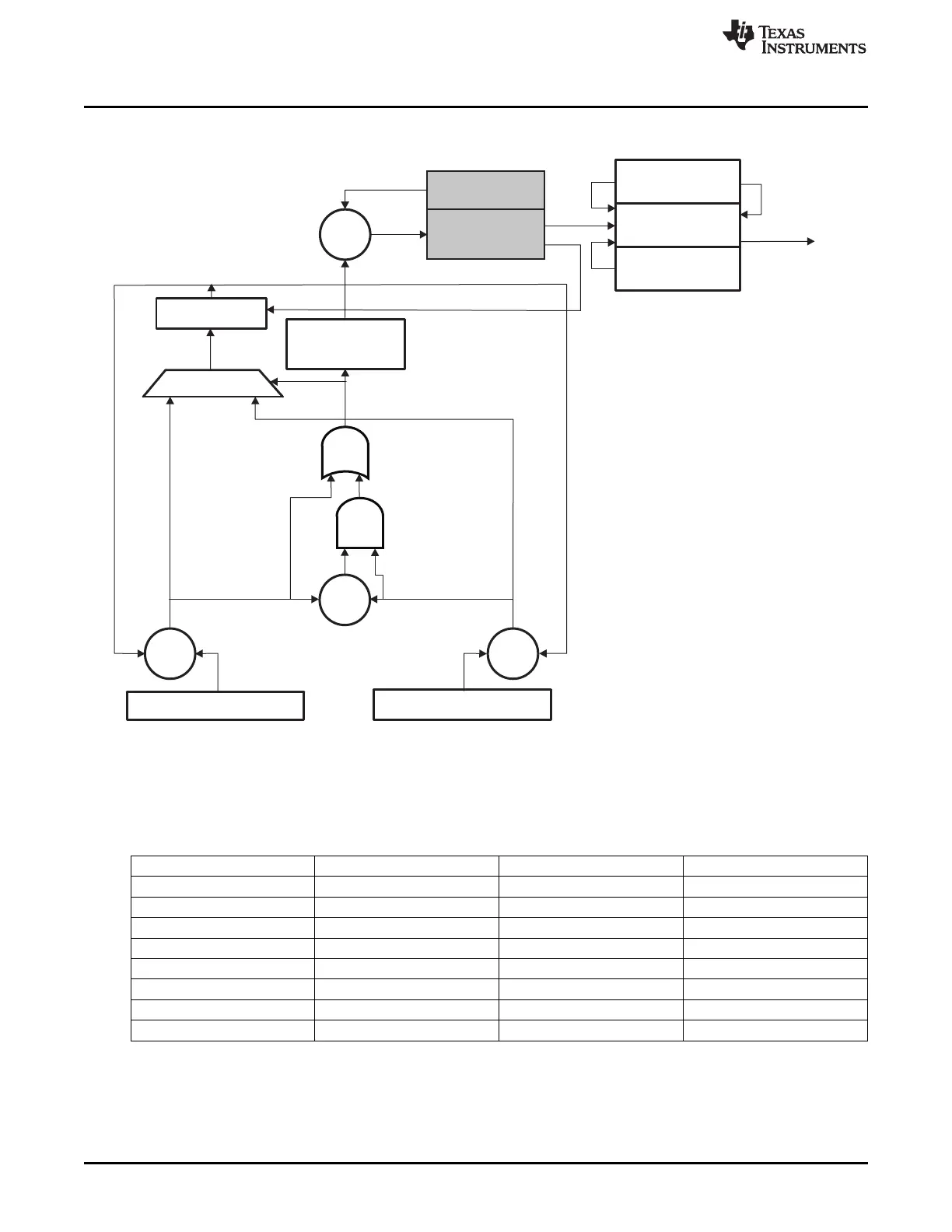
Figure 20-29. 1ms Module Block Diagram
The TPIR, TNIR, TCVR and adders Add1..3 are used to define whether next value loaded in the TCRR
will be value of the TLDR (sub-period value) or the value of TLDR – 1 (over-period value).
The following table shows the value loaded in TCRR according to the sign of the result of Add1, Add2 and
Add3. MSB = ‘0’ means a positive value, MSB = ‘1’ means a negative value.
Table 20-30. Value Loaded in TCRR to Generate 1ms Tick
Add1 MSB Add2 MSB Add3 MSB TCRR
0 0 0 TLDR
0 0 1 TLDR
0 1 0 TLDR
0 1 1 TLDR - 1
1 0 0 N.A.
1 0 1 N.A.
1 1 0 TLDR - 1
1 1 1 TLDR - 1
The values of TPIR and TNIR registers are calculated with formula:
Positive Increment Value = ( ( INTEGER[ Fclk * Ttick ] + 1 ) * 1e6 ) - ( Fclk * Ttick * 1e6 )
Negative Increment Value = ( INTEGER[ Fclk * Ttick ] * 1e6 ) - ( Fclk * Ttick * 1e6 )
where:
3590
Timers SPRUH73H–October 2011–Revised April 2013
Submit Documentation Feedback
Copyright © 2011–2013, Texas Instruments Incorporated

 Loading...


