Multimedia Card Registers
www.ti.com
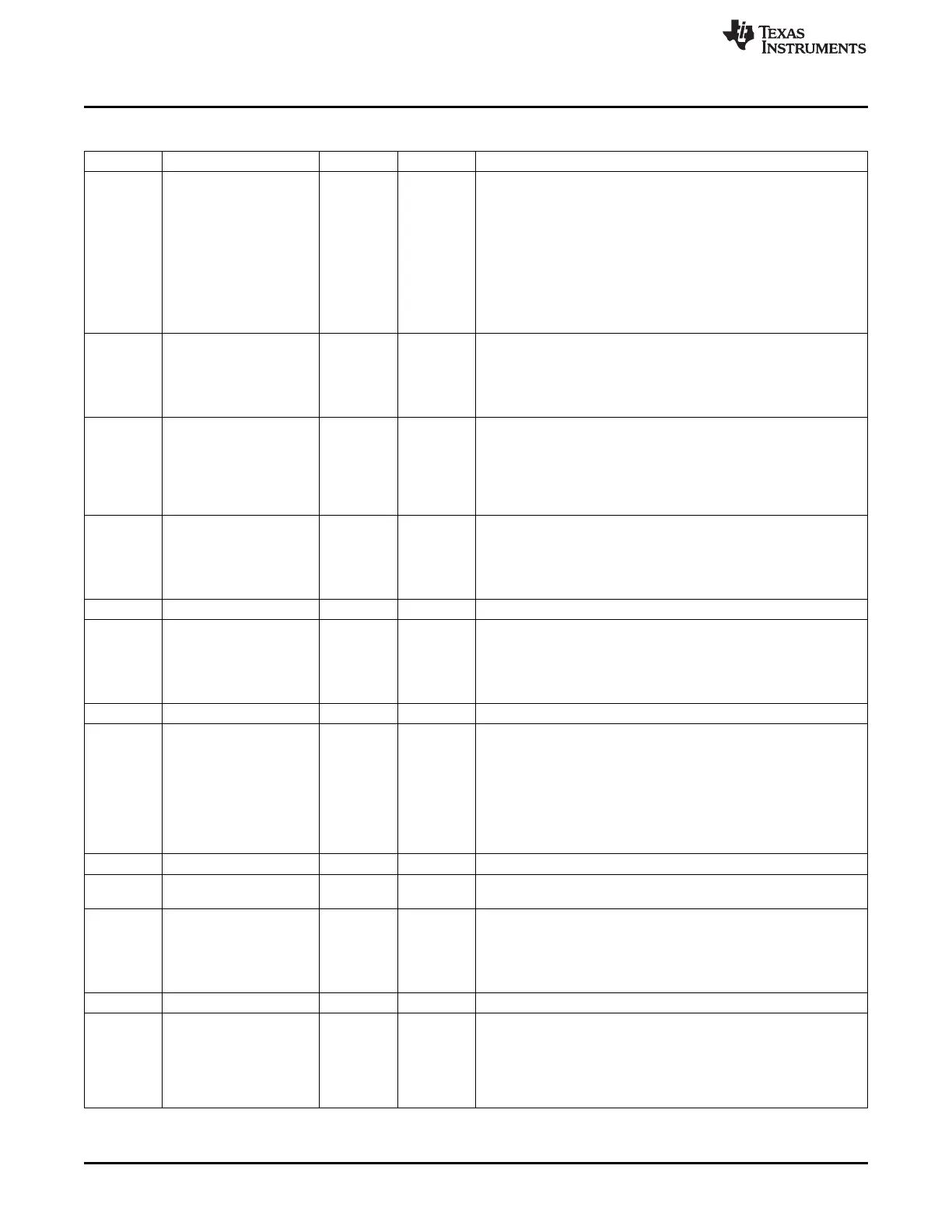
Table 18-42. SD_CAPA Register Field Descriptions (continued)
Bit Field Type Reset Description
24 VS33 R/W 0h Voltage support 3.3V.
Initialization of this register (via a write access to this register)
depends on the system capabilities.
The host driver shall not modify this register after the initialization.
This register is only reinitialized by a hard reset (via mmc_RESET
signal).
0x0(W) = 3.3 V not supported
0x0(R) = 3.3 V not supported
0x1(W) = 3.3 V supported
0x1(R) = 3.3 V supported
23 SRS R 0h Suspend/resume support (SDIO cards only).
This bit indicates whether the host controller supports
Suspend/Resume functionality.
0x0 = The Host controller does not suspend/resume functionality.
0x1 = The Host controller supports suspend/resume functionality.
22 DS R 0h DMA support.
This bit indicates that the Host controller is able to use DMA to
transfer data between system memory and the Host controller
directly.
0x0 = DMA not supported
0x1 = DMA supported
21 HSS R 0h High-speed support.
This bit indicates that the host controller supports high speed
operations and can supply an up-to-52 MHz clock to the card.
0x0 = DMA not supported
0x1 = DMA supported
20 Reserved R 0h
19 AD2S R 0h This bit indicates whether the Host Controller is capable of using
ADMA2.
It depends on setting of generic parameter MADMA_EN.
0x0 = ADMA2 supported
0x1 = ADMA2 not supported
18 Reserved R 0h
17-16 MBL R 0h Maximum block length.
This value indicates the maximum block size that the host driver can
read and write to the buffer in the host controller.
The host controller supports 512 bytes and 1024 bytes block
transfers.
0x0 = 512 bytes
0x1 = 1024 bytes
0x2 = 2048 bytes
15-14 Reserved R 0h
13-8 BCF R 0h Base clock frequency for clock provided to the card.
ARRAY(0x1bfe1b0)
7 TCU R 0h Timeout clock unit.
This bit shows the unit of base clock frequency used to detect Data
Timeout Error (SD_STAT[20] DTO bit).
0x0 = kHz
0x1 = MHz
6 Reserved R 0h
5-0 TCF R 0h Timeout clock frequency.
The timeout clock frequency is used to detect Data Timeout Error
(SD_STAT[20] DTO bit).
0x0 = The timeout clock frequency depends on the frequency of the
clock provided to the card. The value of the timeout clock frequency
is not available in this register.
3438
Multimedia Card (MMC) SPRUH73H–October 2011–Revised April 2013
Submit Documentation Feedback
Copyright © 2011–2013, Texas Instruments Incorporated

 Loading...


