Power, Reset, and Clock Management
www.ti.com
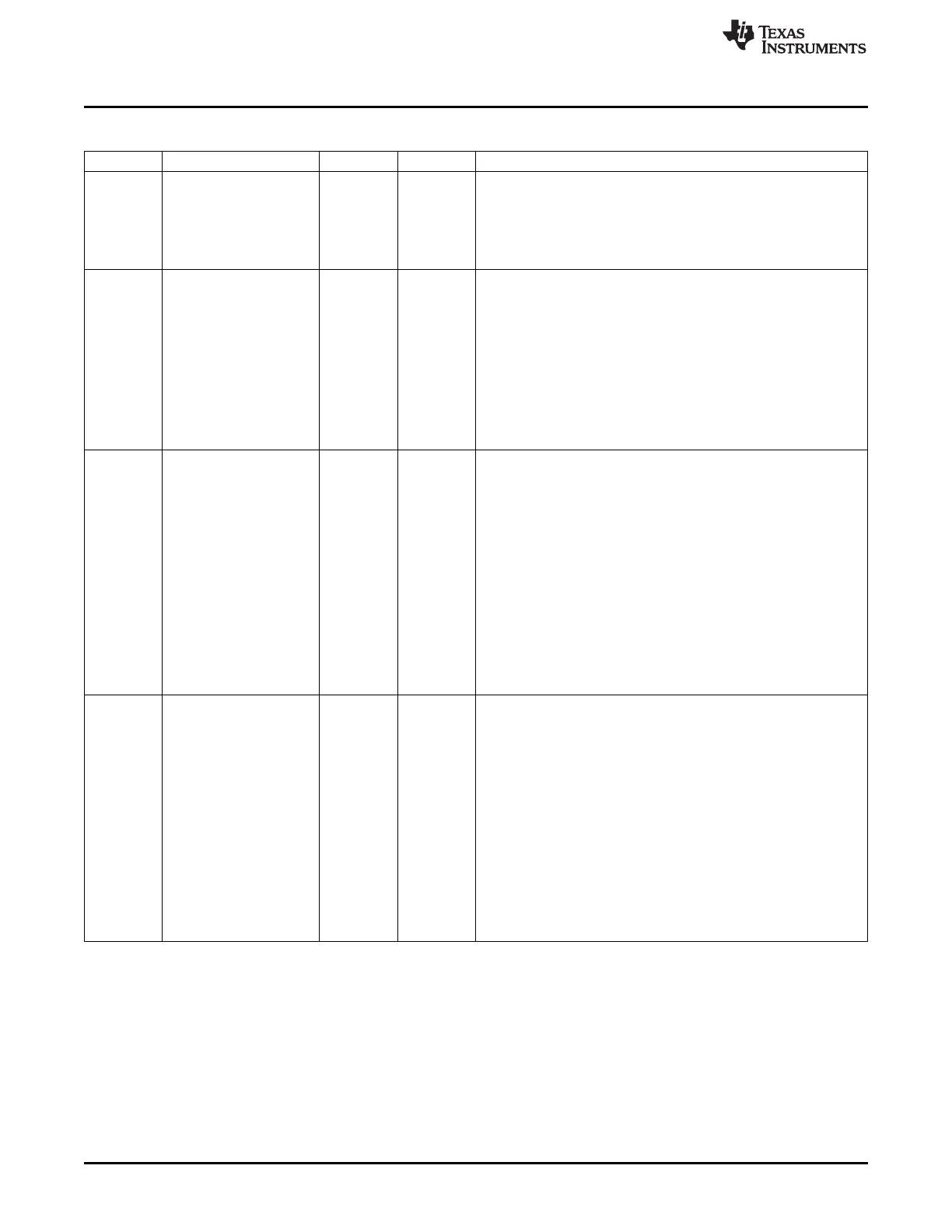
Table 8-129. CM_CLKMODE_DPLL_DDR Register Field Descriptions (continued)
Bit Field Type Reset Description
8 DPLL_DRIFTGUARD_EN R/W 0h This bit allows to enable or disable the automatic recalibration
feature of the DPLL.
The DPLL will automatically start a recalibration process upon
assertion of the DPLL's RECAL flag if this bit is set.
0x0 = Diasbled : DRIFTGUARD feature is disabled
0x1 = Enabled : DRIFTGUARD feature is enabled
7-5 DPLL_RAMP_RATE R/W 0h
Selects the time in terms of DPLL REFCLKs spent at each stage of
the clock ramping process
0x0 = REFCLKx2 : 2 REFCLKs
0x1 = REFCLKx4 : 4 REFCLKs
0x2 = REFCLKx8 : 8 REFCLKs
0x3 = REFCLKx16 : 16 REFCLKs
0x4 = REFCLKx32 : 32 REFCLKs
0x5 = REFCLKx64 : 64 REFCLKs
0x6 = REFCLKx128 : 128 REFCLKs
0x7 = REFCLKx512 : 512 REFCLKs
4-3 DPLL_RAMP_LEVEL R/W 0h The DPLL provides an output clock frequency ramping feature when
switching from bypass clock to normal clock during lock and re-lock.
The frequency ramping will happen in a maximum of 4 steps in
frequency before the DPLL's frequency lock indicator is asserted.
This register is used to enable/disable the DPLL ramping feature.
If enabled, it is also used to select the algorithm used for clock
ramping
0x0 = RAMP_DISABLE : CLKOUT => No ramping CLKOUTX2 =>
No ramping
0x1 = RAMP_ALGO1 : CLKOUT => Bypass clk -> Fout/8 -> Fout/4 -
> Fout/2 -> Fout CLKOUTX2 => Bypass clk -> Foutx2/8 -> Foutx2/4
-> Foutx2/2 -> Foutx2
0x2 = RAMP_ALGO2 : CLKOUT => Bypass clk -> Fout/4 -> Fout/2 -
> Fout/1.5 -> Fout CLKOUTX2 => Bypass clk -> Foutx2/4 ->
Foutx2/2 -> Foutx2/1.5 -> Foutx2
0x3 = Reserved : Reserved
2-0 DPLL_EN R/W 4h DPLL control.
Upon Warm Reset, the PRCM DPLL control state machine updates
this register to reflect MN Bypass mode.
0x0 = Reserved : Reserved
0x1 = Reserved1 : Reserved
0x2 = Reserved2 : Reserved
0x3 = Reserved3 : Reserved
0x4 = DPLL_MN_BYP_MODE : Put the DPLL in MN Bypass mode.
The DPLL_MULT register bits are reset to 0 automatically by putting
the DPLL in this mode.
0x5 = DPLL_LP_BYP_MODE : Put the DPLL in Idle Bypass Low
Power mode.
0x6 = DPLL_FR_BYP_MODE : Put the DPLL in Idle Bypass Fast
Relock mode.
0x7 = DPLL_LOCK_MODE : Enables the DPLL in Lock mode
656
Power, Reset, and Clock Management (PRCM) SPRUH73H–October 2011–Revised April 2013
Submit Documentation Feedback
Copyright © 2011–2013, Texas Instruments Incorporated

 Loading...


