LCD Registers
www.ti.com
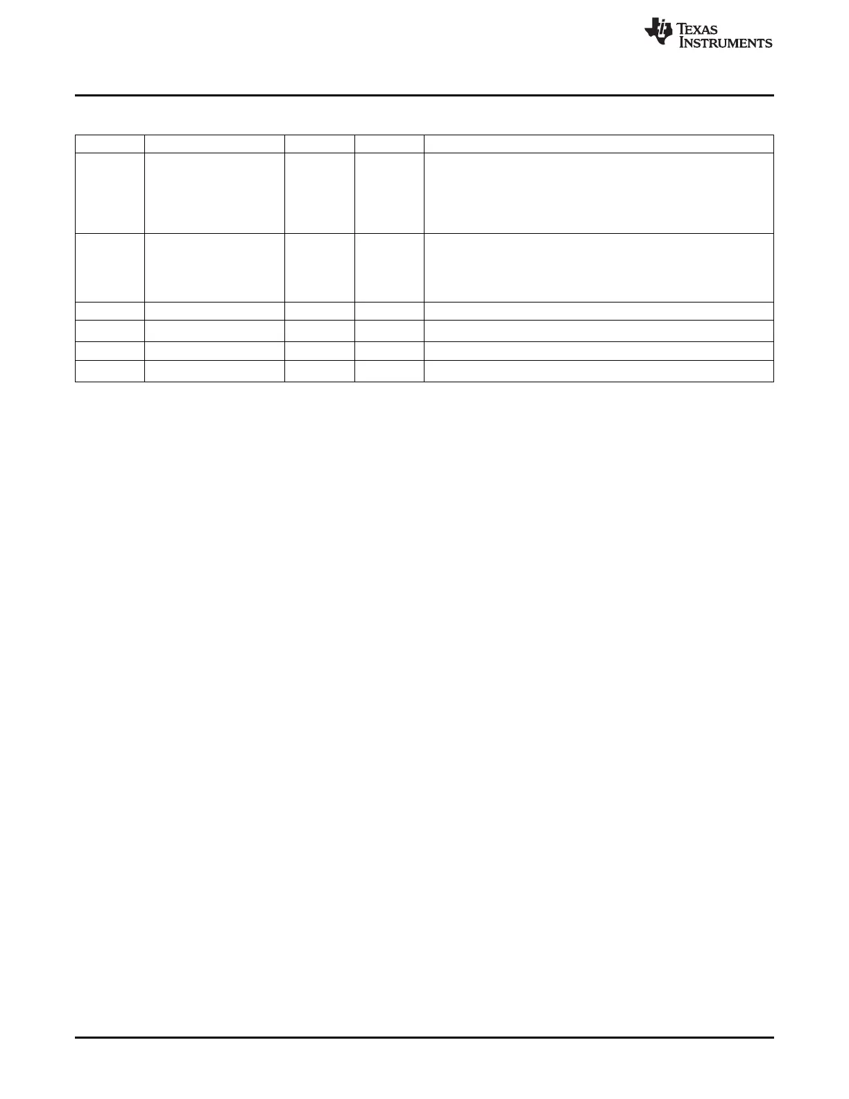
Table 13-26. RASTER_TIMING_2 Register Field Descriptions (continued)
Bit Field Type Reset Description
19-16 acbi R/W 0h AC Bias Pins Transitions per Interrupt Value (from 0 to 15) used to
specify the number of AC Bias pin transitions to count before setting
the line count status (lcs) bit, signaling an interrupt request
Counter frozen when lcd is set, and is restarted when lcs is cleared
by software
This function is disabled when acbi = b'0000'
15-8 acb R/W 0h AC Bias Pin Frequency Value (from 0-255) used to specify the
number of line clocks to count before transitioning the AC Bias pin
This pin is used to periodically invert the polarity of the power supply
to prevent DC charge build-up within the display
acb = Number of line clocks/toggle of the lcd_ac pin
7-6 Reserved R 0h
5-4 hbp_highbits R/W 0h
Bits 9:8 of the horizontal back porch field
3-2 Reserved R 0h
1-0 hfp_highbits R/W 0h
Bits 9:8 of the horizontal front porch field
1144
LCD Controller SPRUH73H–October 2011–Revised April 2013
Submit Documentation Feedback
Copyright © 2011–2013, Texas Instruments Incorporated

 Loading...


