PBD(0) PBD(1) PBD(2)
Queue 0: USB0 EP1 RXSQ
Head
. . .
. . . . . . . . .
Queue 109: USB0 EP1 RXCQ
Head
. . .
PBD(2)
Buffer Descriptor
(1)
Buffer
PBD(1)
Buffer Descriptor
(1)
Buffer pointer
Next descriptor pointer
Buffer size (256)
Data
Buffer
(N)
PBD(3)
Buffer Descriptor
(2)
Buffer
Buffer pointer
Next descriptor pointer
Buffer size (256)
Buffer pointer
Next descriptor pointer
Buffer size (256)
Tail
Tail
Functional Description
www.ti.com
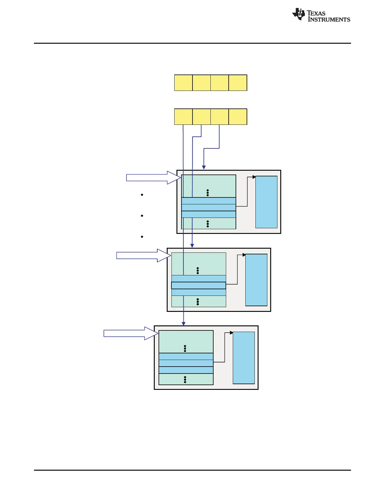
Figure 16-20. Receive Buffer Descriptors and Queue Status Configuration
16.3.9.9.2.1 Receive Initialization (Step 1)
1. The CPU initializes Queue Manager with the Memory Region 0 base address and Memory Region 0
size, Link RAM0 Base address, Link RAM0 data size, and Link RAM1 Base address.
2. The CPU creates BDs, and DBs in main memory and link them creating a BD and DB pairs.
3. CPU then initializes the RXCQ queue and configures the Queue Manager, Channel Setup, DMA
Scheduler, and USB 2.0 Core.
4. It then adds (pushes) the address of the addresses/pointers of three Buffer Descriptors (PBDs) into the
1756
Universal Serial Bus (USB) SPRUH73H–October 2011–Revised April 2013
Submit Documentation Feedback
Copyright © 2011–2013, Texas Instruments Incorporated

 Loading...


