ClkActivationTime = 1
FCLK
CLK
tIACC (access time on memory side)
AccessTime = 10
Data Setup
nADV
AdvRdOffTime = 2
Access Completion
last burst access
RdCycleTime = 11
nCS
nOE
Valid Address
D0 D1 D2 D3
A/D bus
2nd burst access
3rd
CsReadOffTime = RdCycleTime
OeOffTime = RdCycleTime
OeOnTime = 3
GPMC
www.ti.com
Table 7-47. Calculating GPMC Timing Parameters
Number of
Clock Cycles
Parameter Name on (F = 104
GPMC Side Formula Duration (ns) MHz) GPMC Register Configurations
GPMC FCLK Divider - - - GPMCFCLKDIVIDER = 0
ClkActivationTime min ( tCES, tACS) 3 1 CLKACTIVATIONTIME = 1
10 :
roundmax (ClkActivationTime + 94,03: (9,615 + roundmax
RdAccessTime ACCESSTIME = Ah
tIACC + DataSetupTime) 80 + 4,415) (94,03 /
9,615)
PageBurstAccessTime roundmax (tBACC) roundmax (5,2) 1 PAGEBURSTACCESSTIME = 1
101, 03: (94, 03
RdCycleTime AccessTime + max ( tCEZ, tOEZ) 11 RDCYCLETIME = Bh
+ 7)
CsOnTime tCES 0 0 CSONTIME = 0
CsReadOffTime RdCycleTime - 11 CSRDOFFTIME = Bh
AdvOnTime tAVC 0 0 ADVONTIME = 0
AdvRdOffTime tAVD + tAVC 12 2 ADVRDOFFTIME = 2h
(ClkActivationTime + tACH) <
OeOnTime OeOnTime < (ClkActivationTime - 3, for instance OEONTIME = 3h
+ tIACC)
OeOffTime RdCycleTime - 11 OEOFFTIME = Bh
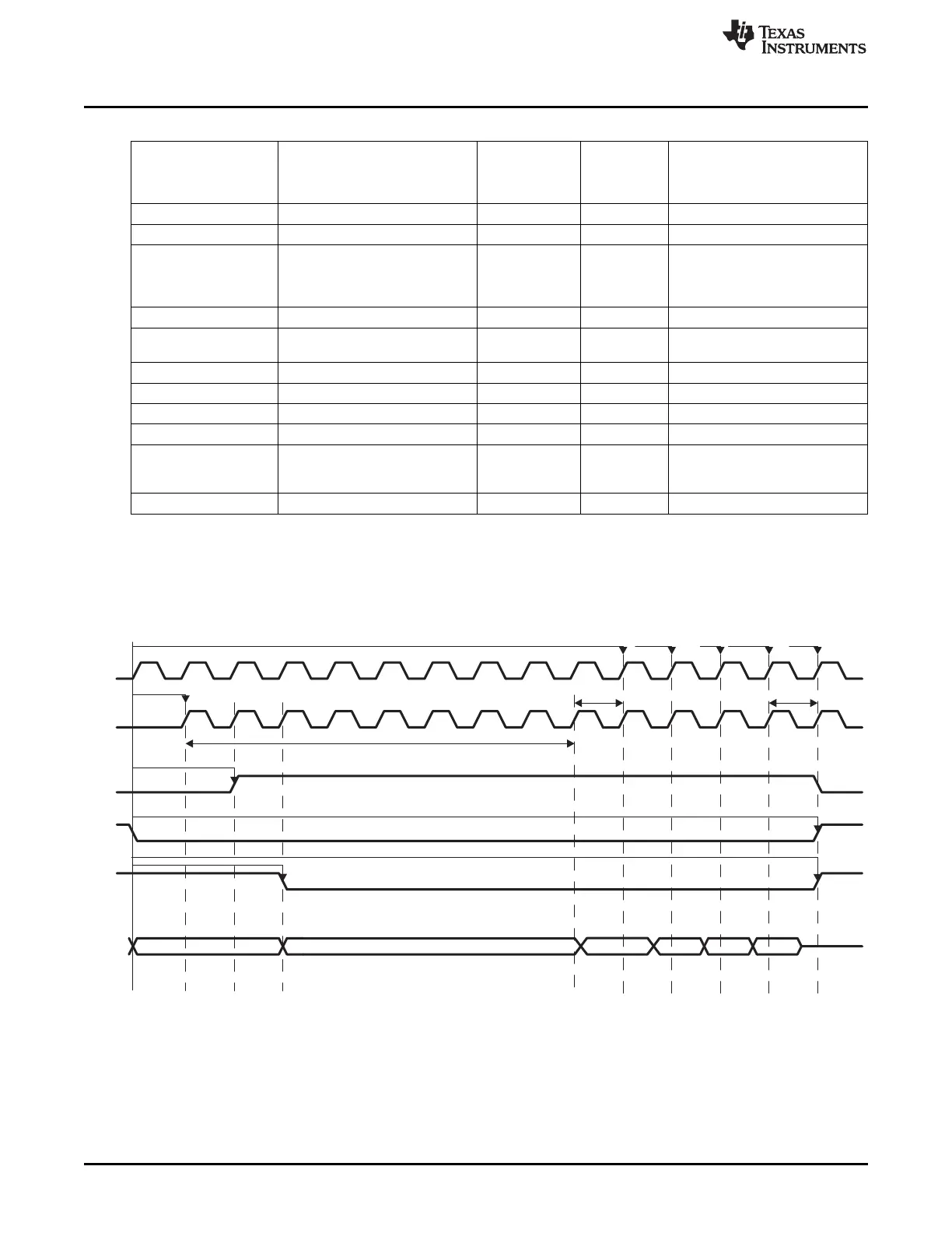
Figure 7-48. Synchronous Burst Read Access (Timing Parameters in Clock Cycles)
358
Memory Subsystem SPRUH73H–October 2011–Revised April 2013
Submit Documentation Feedback
Copyright © 2011–2013, Texas Instruments Incorporated

 Loading...


