www.ti.com
McSPI Registers
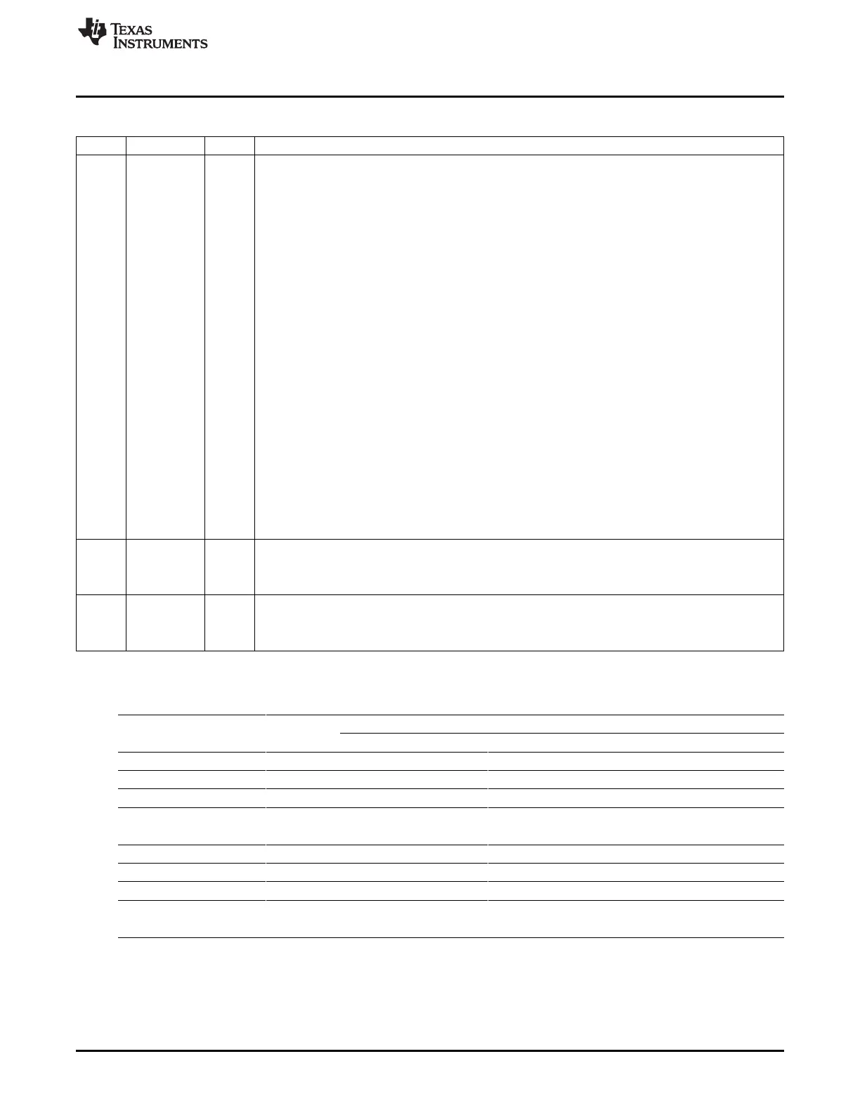
Table 24-18. McSPI Channel (i) Configuration Register (MCSPI_CH(i)CONF) Field Descriptions (continued)
Bit Field Value Description
5-2 CLKD Frequency divider for SPICLK. (only when the module is a Master SPI device). A programmable clock
divider divides the SPI reference clock (CLKSPIREF) with a 4-bit value, and results in a new clock
SPICLK available to shift-in and shift-out data. By default the clock divider ratio has a power of two
granularity when MCSPI_CHCONF[CLKG] is cleared, Otherwise this register is the 4 LSB bit of a 12-bit
register concatenated with clock divider extension MCSPI_CHCTRL[EXTCLK] register.
The value description below defines the clock ratio when MCSPI_CHCONF[CLKG] is cleared to 0.
0 Divide by 1.
1h 2
2h 4
3h 8
4h 16
5h 32
6h 64
7h 128
8h 256
9h 512
Ah 1024
Bh 2048
Ch 4096
Dh 8192
Eh 16384
Fh 32768
1 POL SPICLK polarity
0 SPICLK is held high during the active state
1 SPICLK is held low during the active state
0 PHA SPICLK phase
0 Data are latched on odd numbered edges of SPICLK
1 Data are latched on even numbered edges of SPICLK
Table 24-19. Data Lines Configurations
TRMi
ISi DPEi1 DPEi0 Transmit and Receive Receive Only Transmit Only
0 0 0 Supported Supported Supported
0 0 1 Supported Supported Supported
0 1 0 Supported Supported Supported
0 1 1 Not supported Supported Not supported
(unpredictable result) (unpredictable result)
1 0 0 Supported Supported Supported
1 0 1 Supported Supported Supported
1 1 0 Supported Supported Supported
1 1 1 Not supported Supported Not supported
(unpredictable result) (unpredictable result)
4049
SPRUH73H–October 2011–Revised April 2013 Multichannel Serial Port Interface (McSPI)
Submit Documentation Feedback
Copyright © 2011–2013, Texas Instruments Incorporated

 Loading...


