Vdd
Varray
Memory array
power switch
Memory
Logic
Memory
logic
Power domain
Memory logic
power switch
Logic power
switch
PRCM
PM
Flip-flop
logic
Logic power
switch
Memory
array
Memory bank
prcm-008
Memory
array
Flip-flop
logic
www.ti.com
Power, Reset, and Clock Management
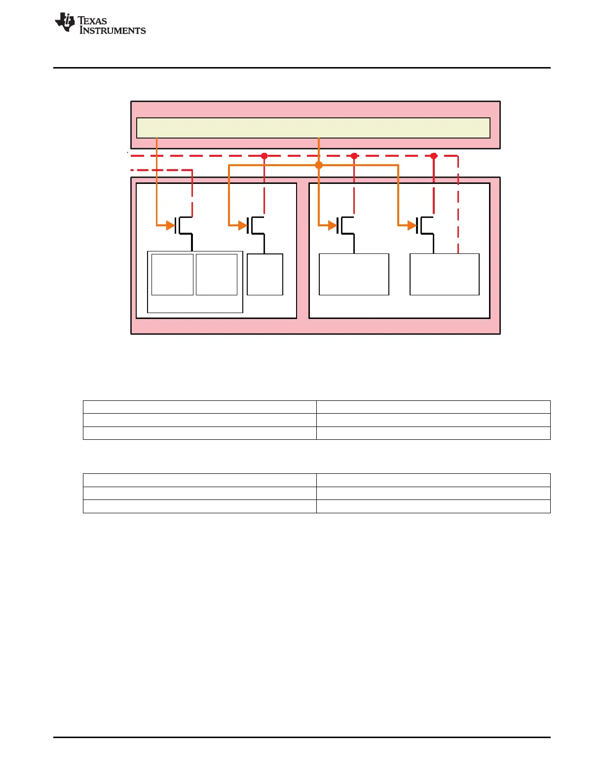
Figure 8-4. Generic Power Domain Architecture
To minimize device power consumption, the modules are grouped into power domains. A power domain
can be split into a logic area and a memory area.
Table 8-10. States of a Memory Area in a Power Domain
State Description
ON The memory array is powered and fully functional
OFF The memory array is powered down
Table 8-11. States of a Logic Area in a Power Domain
State Description
ON Logic is fully powered
OFF Logic power switches are off. All the logic (DFF) is lost
507
SPRUH73H–October 2011–Revised April 2013 Power, Reset, and Clock Management (PRCM)
Submit Documentation Feedback
Copyright © 2011–2013, Texas Instruments Incorporated

 Loading...


