CDET_EXTCTL
CHGDET_RSTRT
CHGDET_DIS
CM_PWRDN
Device
USB PHY
Control Module
USB_CTRLx
USBx_CE
VDDA3P3V_USBx
VBUS
DP
DM
ID
GND
LDO
PMIC
Charger
Battery
Charger
Detection
www.ti.com
Functional Description
• The detection circuitry requires only a 3.3-V supply to be present to operate.
• The charger detection also has a manual mode which allows the user to implement the battery
charging specification in software.
9.2.4.4.2.2 Operation
The control module gives the following interface to control the automatic charger detection circuitry:
• USB_CTRLx.CDET_EXTCTL: Turns the automatic detection on/off. Keep this bit 0 to keep the
automatic detection on. Changing this to 1 enables the manual mode.
• USB_CTRLx.CHGDET_RSTRT: Restarts the charger detection state machine. To initiate the charger
detection, change this bit from 1 to 0. If this bit is 1, the charger enable output (CE) is disabled.
• USB_CTRLx.CHGDET_DIS: Enables/disables the charger detection circuitry. Keep this bit 0 to keep
this charger detection enabled. Setting this bit to 1 will power down the charger detection circuitry.
• USB_CTRLx.CM_PWRDN: Powers up/down the PHY which contains the charger detection circuitry.
Clear this bit to 0 to enable power to the PHY.
To start the charger detection during normal operation, ensure that the PHY and charger are enabled and
the automatic detection is turned on. Then, initiate a charger detection cycle by transitioning
CHGDET_RSTRT from 1 to 0. If a Charging Downstream Port or a Dedicated Charging Port is detected,
the charger enable signal (USBx_CE) will be driven high and remain high until the charger is disabled by
either CHGDET_DIS = 1 or CHGDET_RSTRT=1. If the port remains unconnected after intiating the
charger detect cycle, it will continue the detection until a charger is detected or an error condition occurs.
Note that USBx_CE is not an open drain output.
To disable the charger after successful detection, you must disable the charger detect circuitry with
CHGDET_DIS or CHGDET_RSTRT, even if the charger is physically disconnected.
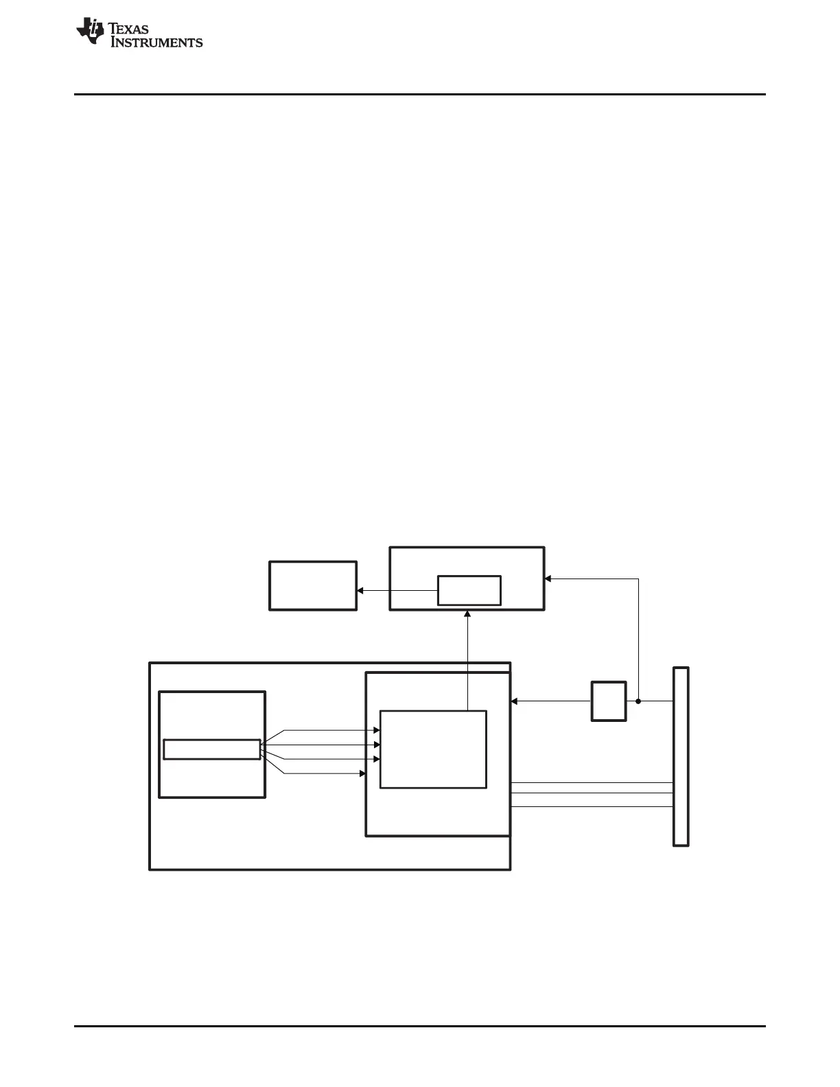
Figure 9-2. USB Charger Detection
Charger detection can be automatically started with no power to the rest of AM335x. If VDDA3P3V_USBx
is present, via an LDO powered by VBUS connected to a host, the charger detection state machine will
automatically start and perform detection. If a charger is detected, USBx_CE will be driven high, otherwise
it will be driven low.
The charger detection circuitry performs the following steps of the Battery Charging specification v1.1:
1. VBUS Detect
2. Data Contact Detect
751
SPRUH73H–October 2011–Revised April 2013 Control Module
Submit Documentation Feedback
Copyright © 2011–2013, Texas Instruments Incorporated

 Loading...


