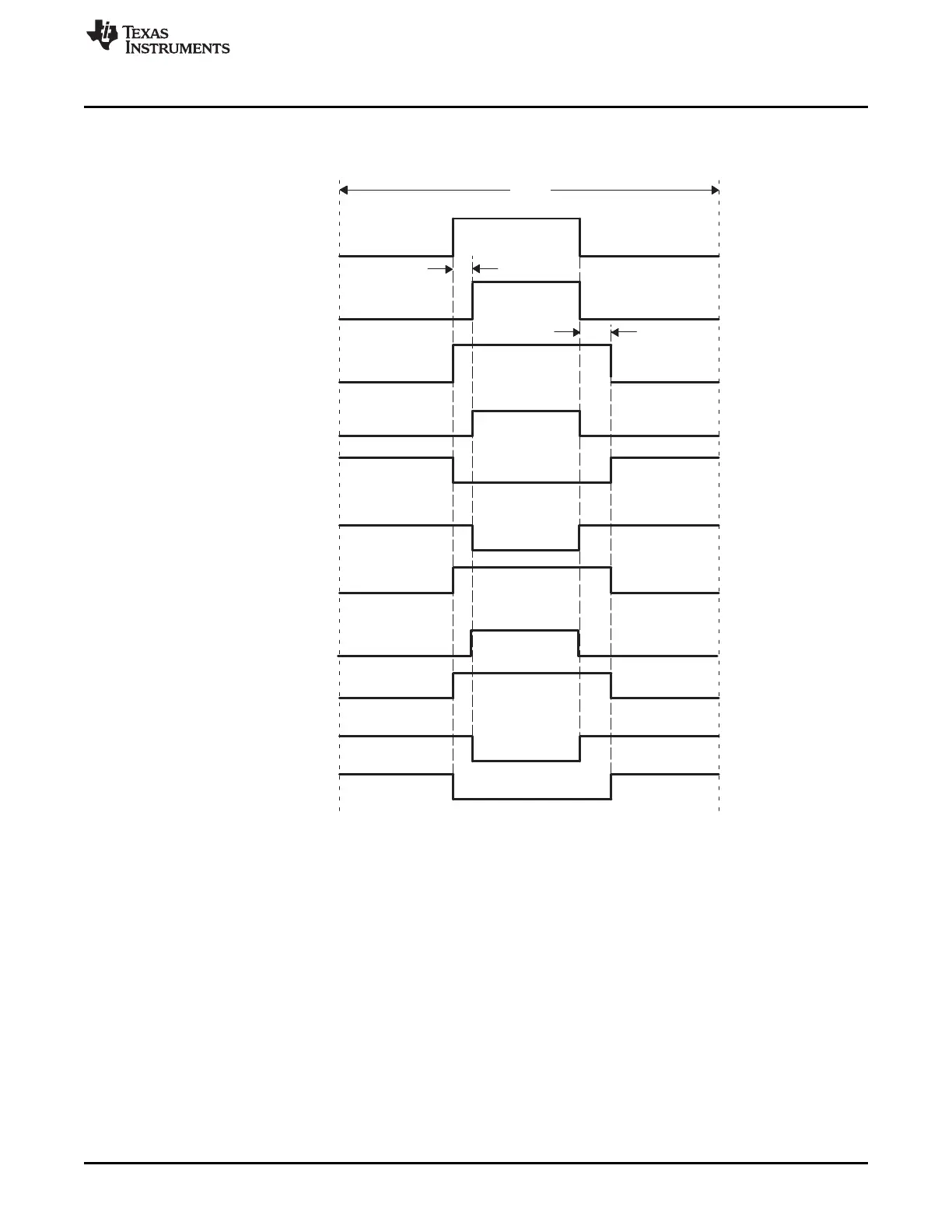
Original
(outA)
Rising Edge
Delayed (RED)
Falling Edge
Delayed (FED)
Active High
Complementary
(AHC)
Active Low
Complementary
(ALC)
Active High
(AH)
Active Low
(AL)
RED
FED
Period
www.ti.com
Enhanced PWM (ePWM) Module
Figure 15-35 shows waveforms for typical cases where 0% < duty < 100%.
Figure 15-35. Dead-Band Waveforms for Typical Cases (0% < Duty < 100%)
The dead-band submodule supports independent values for rising-edge (RED) and falling-edge (FED)
delays. The amount of delay is programmed using the DBRED and DBFED registers. These are 10-bit
registers and their value represents the number of time-base clock, TBCLK, periods a signal edge is
delayed by. For example, the formula to calculate falling-edge-delay and rising-edge-delay are:
FED = DBFED × T
TBCLK
RED = DBRED × T
TBCLK
Where T
TBCLK
is the period of TBCLK, the prescaled version of SYSCLKOUT.
1537
SPRUH73H–October 2011–Revised April 2013 Pulse-Width Modulation Subsystem (PWMSS)
Submit Documentation Feedback
Copyright © 2011–2013, Texas Instruments Incorporated

 Loading...


