Tpwm = 800 ns
324 ns
30 31 32 33 34
10 ns steps
37.5%
38.8%
40.0%
41.3%
42.5%
Demanded
duty (40.5%)
EPWM1A
0 79
Enhanced PWM (ePWM) Module
www.ti.com
15.2.2.10.5.1 Edge Positioning
In a typical power control loop (switch modes, digital motor control (DMC), uninterruptible power supply
(UPS)), a digital controller (PID, 2pole/2zero, lag/lead, etc.) issues a duty command, usually expressed in
a per unit or percentage terms.
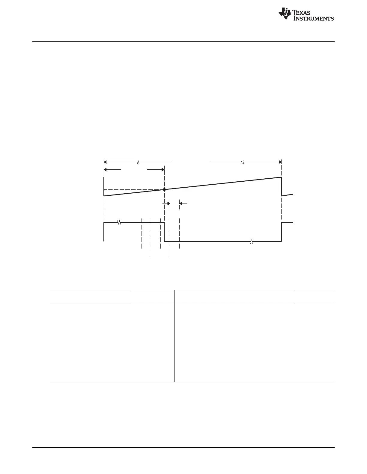
In the following example, assume that for a particular operating point, the demanded duty cycle is 0.405 or
40.5% on-time and the required converter PWM frequency is 1.25 MHz. In conventional PWM generation
with a system clock of 100 MHz, the duty cycle choices are in the vicinity of 40.5%. In Figure 15-51, a
compare value of 32 counts (duty = 40%) is the closest to 40.5% that you can attain. This is equivalent to
an edge position of 320 ns instead of the desired 324 ns. This data is shown in Table 15-42.
By utilizing the MEP, you can achieve an edge position much closer to the desired point of 324 ns.
Table 15-42 shows that in addition to the CMPA value, 22 steps of the MEP (CMPAHR register) will
position the edge at 323.96 ns, resulting in almost zero error. In this example, it is assumed that the MEP
has a step resolution of 180 ns.
Figure 15-51. Required PWM Waveform for a Requested Duty = 40.5%
Table 15-42. CMPA vs Duty (left), and [CMPA:CMPAHR] vs Duty (right)
CMPA DUTY High Time CMPA CMPAHR Duty High Time
(count)
(1) (2) (3)
(%) (ns) (count) (count) (%) (ns)
28 35.0 280 32 18 40.405 323.24
29 36.3 290 32 19 40.428 323.42
30 37.5 300 32 20 40.450 323.60
31 38.8 310 32 21 40.473 323.78
32 40.0 320 32 22 40.495 323.96
33 41.3 330 32 23 40.518 324.14
34 42.5 340 32 24 40.540 324.32
32 25 40.563 324.50
Required 32 26 40.585 324.68
32.40 40.5 324 32 27 40.608 324.86
(1)
System clock, SYSCLKOUT and TBCLK = 100 MHz, 10 ns
(2)
For a PWM Period register value of 80 counts, PWM Period = 80 × 10 ns = 800 ns, PWM frequency = 1/800 ns = 1.25 MHz
(3)
Assumed MEP step size for the above example = 180 ps
1554
Pulse-Width Modulation Subsystem (PWMSS) SPRUH73H–October 2011–Revised April 2013
Submit Documentation Feedback
Copyright © 2011–2013, Texas Instruments Incorporated

 Loading...


