GPMC_FCLK
GPMC_CLK
Valid address
D 0
A
K
D
E
E
F
G
G
H
C
B
B
nBE1/nBE0
D
A
nCS
nADV
nOE
GPMC
www.ti.com
For WEn rising edge (WEn de-activated):
• Case where [1-0] GPMCFCLKDIVIDER = 0x0
I = 0.5 * WEEXTRADELAY * GPMC_FCLK period
• Case where GPMCFCLKDIVIDER = 0x1
I = 0.5 * WEEXTRADELAY * GPMC_FCLK period, when (CLKACTIVATIONTIME and WEOFFTIME
are odd) or (CLKACTIVATIONTIME and WEOFFTIME are even)
I = (1 + 0.5 * WEEXTRADELAY) * GPMC_FCLK period otherwise
• Case where GPMCFCLKDIVIDER = 0x2
I = 0.5 * WEEXTRADELAY * GPMC_FCLK period, when (WEOFFTIME - CLKACTIVATIONTIME) is a
multiple of 3
I = (1 + 0.5 * WEEXTRADELAY) * GPMC_FCLK period, when (WEOFFTIME - CLKACTIVATIONTIME
- 1) is a multiple of 3
I = (2 + 0.5 * WEEXTRADELAY) * GPMC_FCLK period, when (WEOFFTIME - CLKACTIVATIONTIME
- 2) is a multiple of 3
For GPMC_ADVn low pulse duration:
• Read operation
K = (ADVRDOFFTIME - ADVONTIME) * (TIMEPARAGRANULARITY + 1) * GPMC_FCLK period
• Write operation
K = (ADVWROFFTIME - ADVONTIME) * (TIMEPARAGRANULARITY + 1) * GPMC_FCLK period
For GPMC_WAIT invalid to first data latching GPMC_CLK edge:
L = WAITMONITORINGTIME * (GPMCFCLKDIVIDER + 1) * GPMC_FCLK period + GPMC_CLK
period
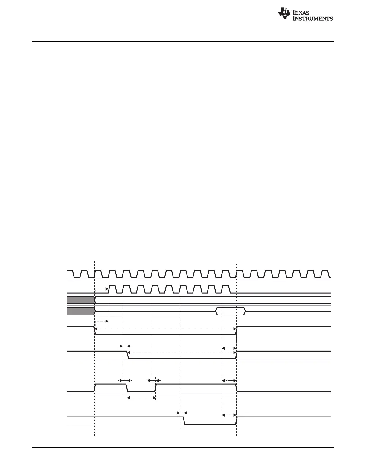
Figure 7-45 shows a synchronous NOR single read simplified example where formulas are associated
with signal waves.
Figure 7-45. Synchronous NOR Single Read Simplified Example
352
Memory Subsystem SPRUH73H–October 2011–Revised April 2013
Submit Documentation Feedback
Copyright © 2011–2013, Texas Instruments Incorporated
 Loading...


