www.ti.com
Functional Description
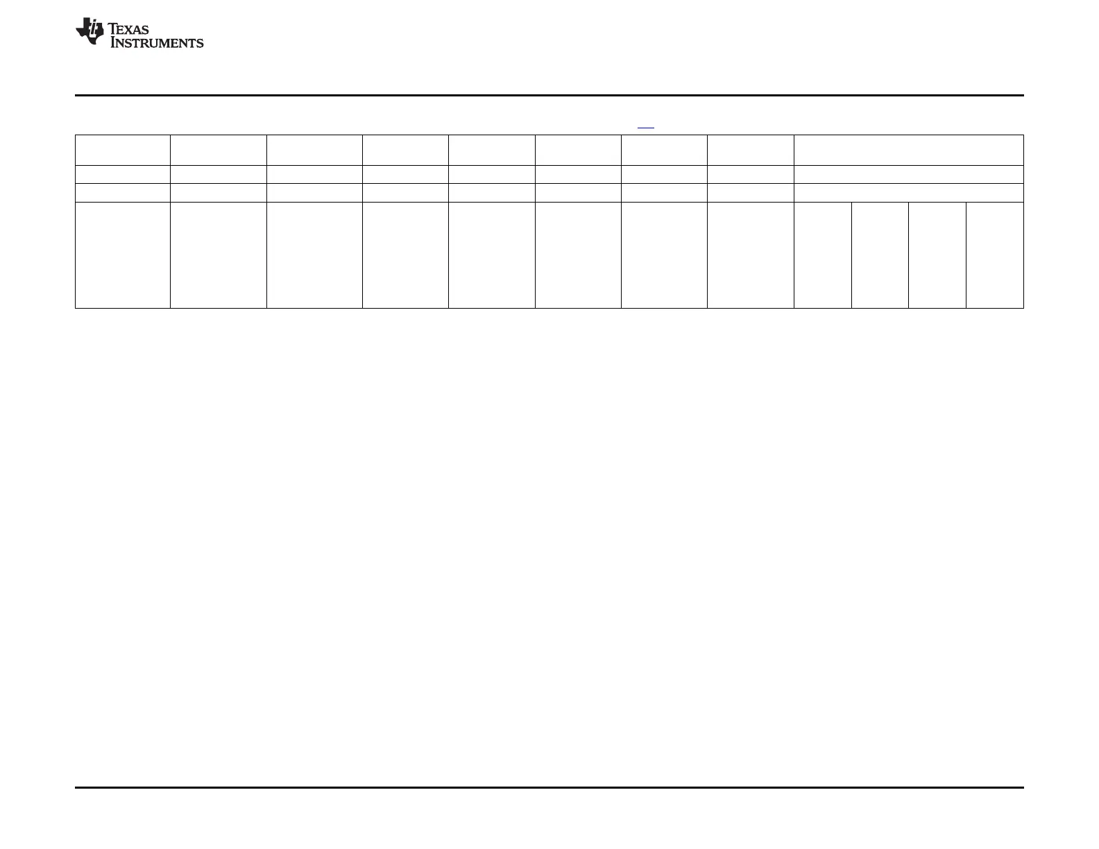
Table 26-7. SYSBOOT Configuration Pins[4] (continued)
SYSBOOT[15:14 SYSBOOT[13:12 SYSBOOT[11:10 SYSBOOT[9] SYSBOOT[8] SYSBOOT[7:6] SYSBOOT[5] SYSBOOT[4:0] Boot Sequence
] ] ]
11101b Reserved
11110b Reserved
00b 11111b Fast EMAC1 UART0 Reserved
00b = 19.2MHz For Fast For Fast 0 = 8-bit device 00b = MII 0 = CLKOUT1
(all other values External
External Boot: External Boot: disabled
01b = 24MHz 1 = 16-bit 01b = RMII
reserved) Boot
must be 0b
00b = non-muxed device 1 = CLKOUT1
10b = 25MHz 10b =
device enabled
Reserved
11b = 26MHz
10b = muxed
11b = RGMII
device
w/o internal
x1b = reserved delay
SYSBOOT Configuration Pins Notes:
1. WAIT is monitored on GPMC_WAIT0.
2. MUX1 and MUX2 designate which group of XIP signals are used. Each group is defined in Table 26-9.
3. Note that even though some bits may be a "don't care" for ROM code, all SYSBOOT values are latched into the CONTROL_STATUS register
and may be used by software after ROM execution has completed.
4. SYSBOOT[15:0] terminals are respectively LCD_DATA[15:0] inputs, latched on the rising edge of PWRONRSTn.
4111
SPRUH73H–October 2011–Revised April 2013 Initialization
Submit Documentation Feedback
Copyright © 2011–2013, Texas Instruments Incorporated

 Loading...


