UP
DOWN
UP
DOWN
2
0
3
4
1
2
3
1
2
0
3
4
1
2
0
3
1
TBCNT
TBCTRDirection
EPWMxA/EPWMxB
Case2:
CMPA =3,25%Duty
Case3:
CMPA =2,50%Duty
Case3:
CMPA =1,75%Duty
Case4:
CMPA =0,100%Duty
Case1:
CMPA =4,0%Duty
EPWMxA/EPWMxB
EPWMxA/EPWMxB
EPWMxA/EPWMxB
EPWMxA/EPWMxB
Mode:Up-DownCount
TBPRD=4
CAU=SET,CAD=CLEAR
0%-100%Duty
www.ti.com
Enhanced PWM (ePWM) Module
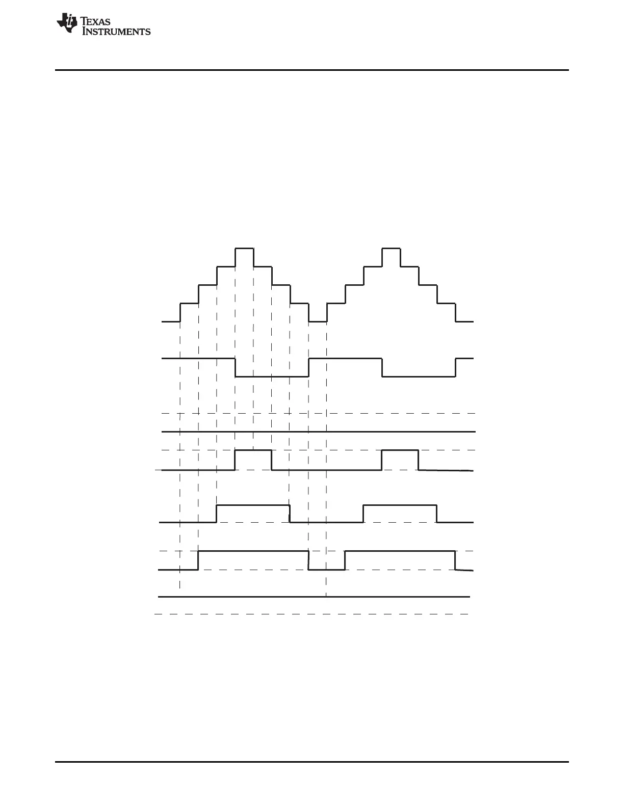
Figure 15-26 shows how a symmetric PWM waveform can be generated using the up-down-count mode
of the TBCNT. In this mode 0%-100% DC modulation is achieved by using equal compare matches on the
up count and down count portions of the waveform. In the example shown, CMPA is used to make the
comparison. When the counter is incrementing the CMPA match will pull the PWM output high. Likewise,
when the counter is decrementing the compare match will pull the PWM signal low. When CMPA = 0, the
PWM signal is low for the entire period giving the 0% duty waveform. When CMPA = TBPRD, the PWM
signal is high achieving 100% duty.
When using this configuration in practice, if you load CMPA/CMPB on zero, then use CMPA/CMPB values
greater than or equal to 1. If you load CMPA/CMPB on period, then use CMPA/CMPB values less than or
equal to TBPRD-1. This means there will always be a pulse of at least one TBCLK cycle in a PWM period
which, when very short, tend to be ignored by the system.
Figure 15-26. Up-Down-Count Mode Symmetrical Waveform
1521
SPRUH73H–October 2011–Revised April 2013 Pulse-Width Modulation Subsystem (PWMSS)
Submit Documentation Feedback
Copyright © 2011–2013, Texas Instruments Incorporated

 Loading...


